Plasma display apparatus

A display device and plasma technology, which is applied in the direction of AC plasma display panels, optical/shielding devices, electrode configurations, etc., can solve the problems of rising manufacturing costs of plasma display panels, reduce initial discharge voltage, and improve discharge diffusion efficiency , Reduce the effect of starting discharge voltage

Inactive Publication Date: 2007-12-05
LG ELECTRONICS INC
View PDF0 Cites 1 Cited by
  • Summary
  • Abstract
  • Description
  • Claims
  • Application Information

AI Technical Summary

Problems solved by technology

The transparent electrodes 11a and 12a cause the increase in the manufacturing cost of the plasma display panel

Method used


Image

  • Plasma display apparatus
  • Plasma display apparatus
  • Plasma display apparatus

Examples


Embodiment Construction

[0032] Hereinafter, the plasma display device according to the present invention will be described in detail with reference to FIGS. 2 to 17b of the accompanying drawings.

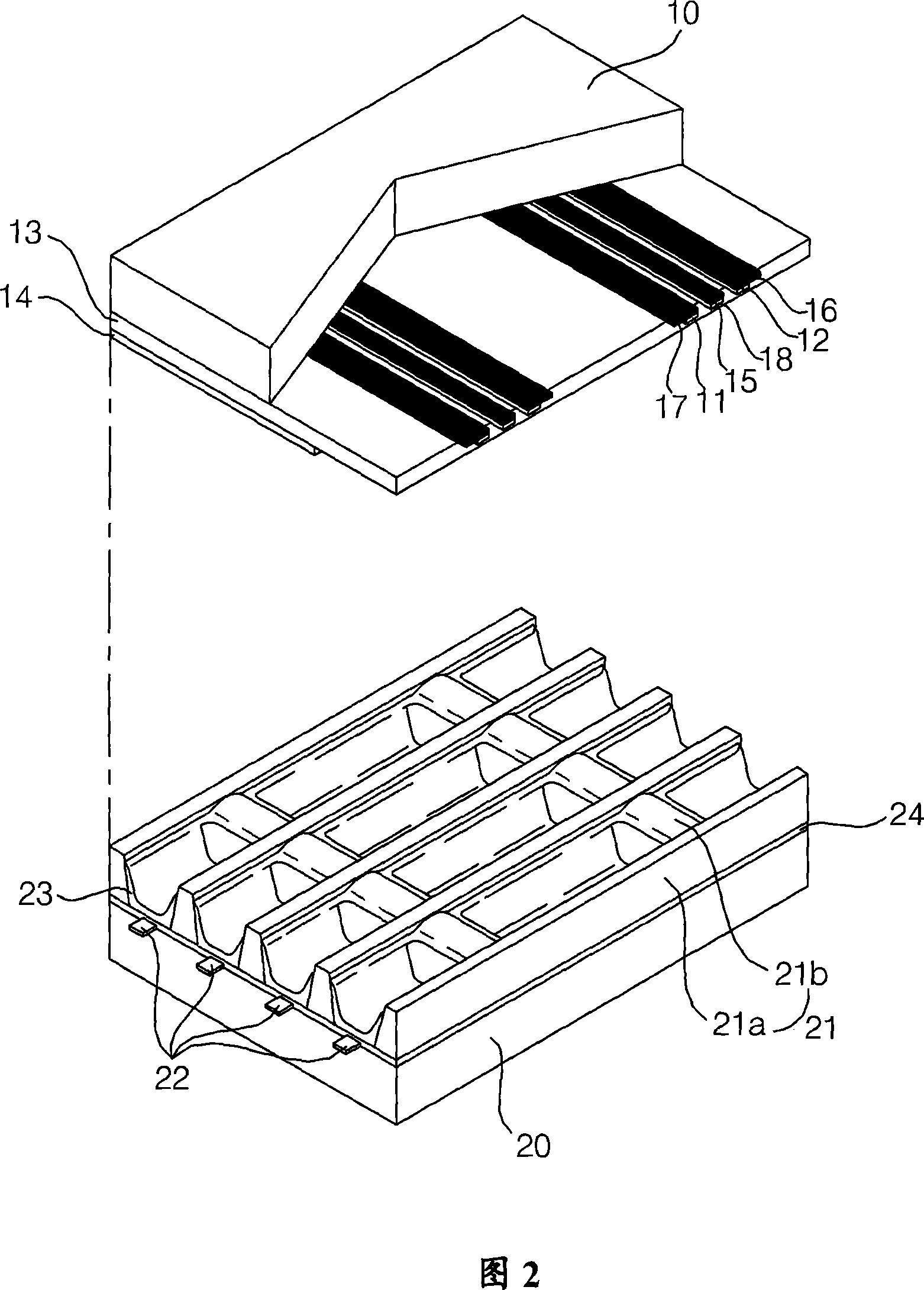
[0033] Hereinafter, the plasma display device according to the present invention will be described in detail with reference to the drawings. 2 is a perspective view showing an embodiment of a panel structure included in the plasma display device according to the present invention.

[0034] As shown in FIG. 2 , the plasma display panel includes: scan electrodes 11 and sustain electrodes 12 formed on an upper substrate 10 as sustain electrode pairs; and address electrodes 22 formed on a lower substrate 20 .

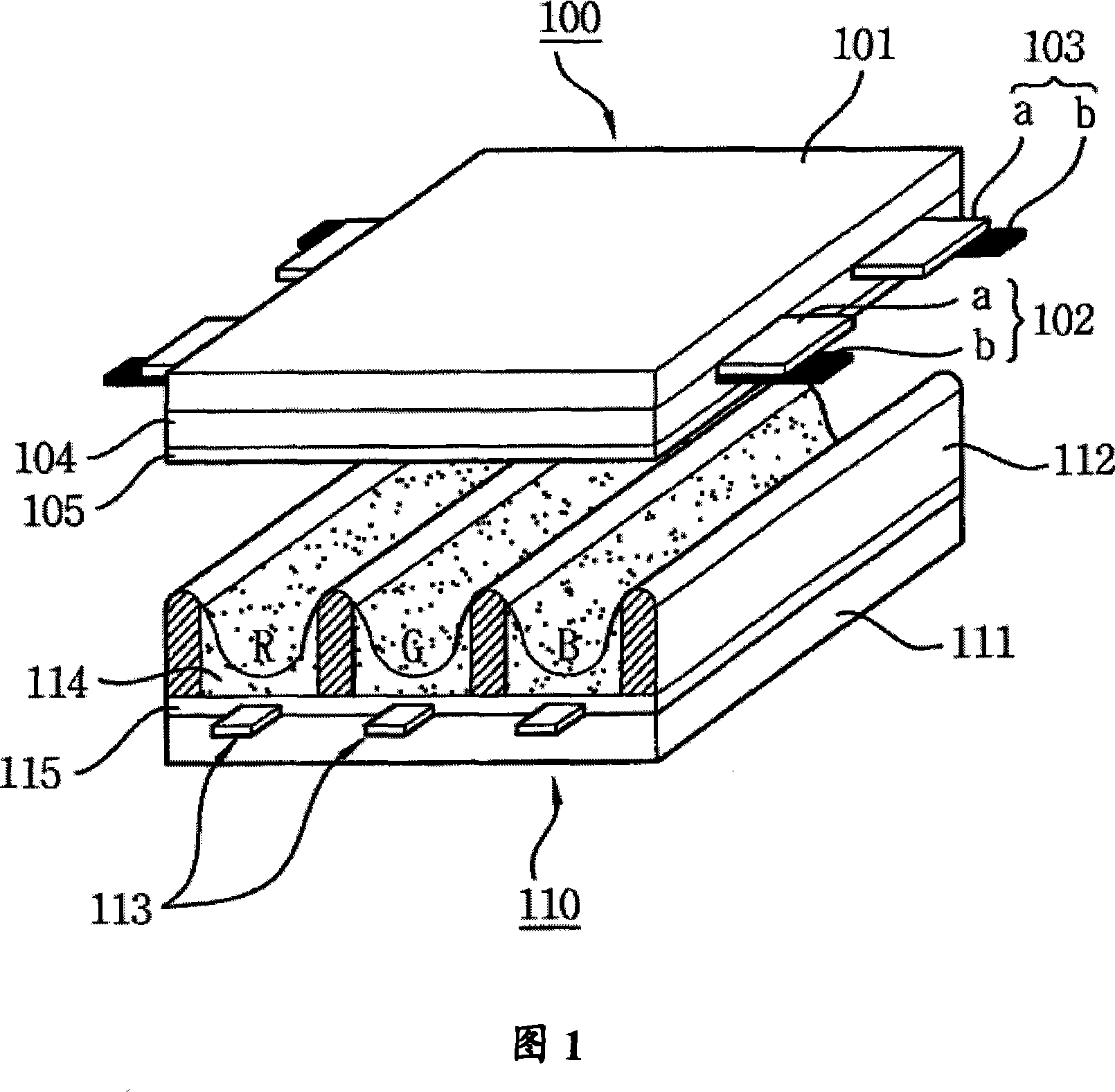
[0035] In the plasma display panel according to the present invention, the sustain electrode pairs 11 and 12 are different from the conventional sustain electrode pair shown in FIG. 1 in that they are formed of opaque metal electrodes. Sustain electrode pairs 11 and 12 are formed using silver (Ag), cop...


PUM


Abstract

A plasma display apparatus is provided. The plasma display apparatus including an upper substrate (10); a plurality of first electrodes and second electrodes (11,12) formed in the upper substrate; a lower substrate (20) arranged to be opposite to the upper substrate; and a plurality of third electrodes and barrier ribs (21) formed in the lower substrate includes a black matrix (15) formed in the upper substrate to be overlapped with the barrier ribs; and a fourth electrode (18) formed on the black matrix (15) to intersect the third electrodes, wherein at least one of the plurality of first and second electrodes is formed in one layer.

Description

technical field [0001] The present invention relates to a plasma display device, and more specifically, to a panel included in a plasma display device. Background technique [0002] Regarding the plasma display panel, the partition wall formed between the upper substrate and the lower substrate forms a unit cell, and each cell is filled with neon (Ne), helium (He) or a mixed gas of neon and helium (Ne+He) Such a main discharge gas and an inert gas containing a small amount of xenon. When discharge is performed by a high-frequency voltage, the inert gas generates vacuum ultraviolet rays (Vacuum Ultraviolet rays), and the phosphors formed between the partition walls emit light to display an image. Such a plasma display panel is attracting attention as a next-generation display device because it can have a thin and light structure. [0003] FIG. 1 is a diagram showing the structure of a general plasma display panel. As shown in FIG. 1 , the upper panel 100 and the lower pane...

Claims


Application Information

Patent Timeline
Patent Type & Authority Applications(China)
IPC IPC(8): H01J17/49H01J17/02H01J17/04H01J11/14H01J11/22H01J11/24H01J11/32H01J11/34H01J11/44
CPCH01J11/28H01J2211/326H01J11/30H01J11/24G09G2310/066H01J2211/444G09G3/2927H01J11/12H01J11/22H01J11/34H01J11/44
Inventor 柳成男全佑坤洪相玟金禹泰姜炅雅咸正现金在声
Owner LG ELECTRONICS INC
Why Eureka
Try Eureka