Plasma display apparatus

A plasma and display technology, applied in the field of plasma display, can solve the problems of rising manufacturing cost of plasma display panels, and achieve the effects of reducing manufacturing cost, improving discharge diffusion efficiency, and reducing initial discharge voltage

Inactive Publication Date: 2012-09-26
LG ELECTRONICS INC
View PDF0 Cites 0 Cited by
  • Summary
  • Abstract
  • Description
  • Claims
  • Application Information

AI Technical Summary

Problems solved by technology

The transparent electrodes 102a and 103a cause an increase in the manufacturing cost of the plasma display panel

Method used


Image

  • Plasma display apparatus
  • Plasma display apparatus
  • Plasma display apparatus

Examples


Embodiment Construction

[0038] Hereinafter, preferred embodiments of the present invention will be described in detail based on the drawings.

[0039] However, it goes without saying that the plasma display according to the present invention is not limited to the embodiments described in this specification, and multiple embodiments are possible.

[0040] Below, refer to the attached figure 2 ~ attached Figure 17 , the plasma display related to the present invention will be described in detail.

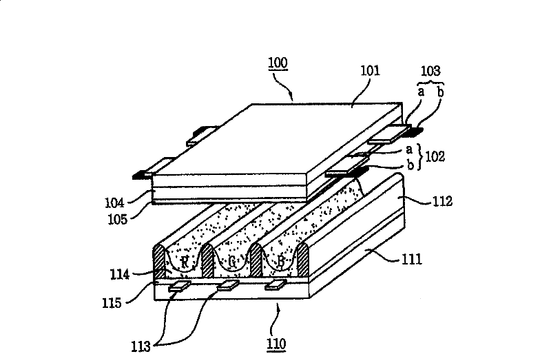
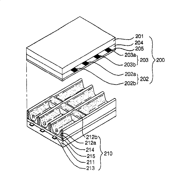
[0041] figure 2 It is a perspective view showing one embodiment of the panel included in the plasma display according to the present invention.

[0042] As shown in the figure, the plasma display panel includes an upper panel 200 and a lower panel 210 bonded at a predetermined interval. Address electrodes 213 formed on lower substrate 211 in a direction intersecting sustain electrode pairs 202 and 203 , and partition walls 212 formed on lower substrate 211 and partition a plurality of discharge cells are...


PUM


Abstract

The present invention relates to a plasma display apparatus. The plasma display apparatus comprises a front substrate; a first electrode, a second electrode and a dielectric layer formed on the front substrate; a rear substrate faced with the front substrate; a third electrode formed on the rear substrate; and a barrier rib which is formed on the rear substrate and patitions discharge cells, wherein at least one of the first electrode and the second electrode is formed with one layer, and the width of at least one of barrier ribs which patition the discharge cells in the outside of an effective display region is wider than the width of barrier ribs which patition the discharge cells in the inside of the effective display region. The plasma display apparatus according to the present invention removes a transparent electrode consisting of ITO to reduce the manufacturing cost of the plasma display panel. By forming projecting electrodes protruded in the direction of the center of the discharge cell or in the opposite direction of the center of the discharge cell from the scan electrode or the sustain electrode line, the firing voltage can be lowered and the discharge diffusion efficiency of the discharge cell can be increased.

Description

technical field [0001] The present invention relates to a plasma display, and more specifically, to a panel included in the plasma display. Background technique [0002] The plasma display panel is a member formed by the partition wall formed between the upper substrate and the lower substrate to form a unit cell, and each cell is filled with neon (Ne), helium (He), or a mixed gas of neon and helium (Ne+ He) and the like main discharge gas and a small amount of xenon (Xe) inert gas. When a high-frequency voltage is used to discharge, the inert gas generates vacuum ultraviolet rays (Vacuum Ultraviolet rays), which make the phosphors formed between the partition walls emit light and display images. Such a plasma display panel is attracting attention as a next-generation display device because it can have a thin and light structure. [0003] figure 1 It is a figure showing the structure of a general plasma display panel. As shown in the figure, the plasma display panel comb...

Claims


Application Information

Patent Timeline
Patent Type & Authority Patents(China)
IPC IPC(8): H01J11/24H01J11/12H01J11/36H01J11/22H01J11/26H01J11/34
CPCH01J11/24H01J11/36H01J2211/245H01J2211/368H01J11/12H01J11/22H01J11/44
Inventor 柳成男全佑坤洪相玟金禹泰姜炅雅咸正现金在声
Owner LG ELECTRONICS INC
Why Eureka
Try Eureka