Plasma display panel

A display panel and plasma technology, which is applied to alternating current plasma display panels, gas discharge electrodes, solid cathode components, etc., can solve problems such as increasing the manufacturing cost of plasma display panels, and achieve the effects of reducing manufacturing costs and increasing aperture ratio

Inactive Publication Date: 2006-10-04
LG ELECTRONICS INC
View PDF0 Cites 4 Cited by
  • Summary
  • Abstract
  • Description
  • Claims
  • Application Information

AI Technical Summary

Problems solved by technology

The transparent electrodes 102a and 103a become a cause of increasing the manufacturing cost of the plasma display panel

Method used


Image

  • Plasma display panel
  • Plasma display panel
  • Plasma display panel

Examples


no. 1 example

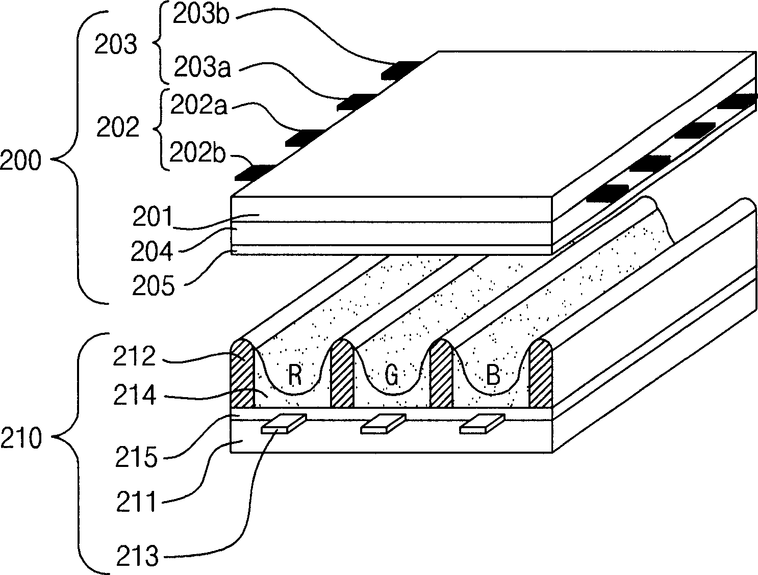
[0052] figure 2 A plasma display panel according to a first embodiment of the present invention is illustrated.

[0053] Such as figure 2 As shown, the plasma display panel according to the first embodiment of the present invention includes a front panel 200 and a rear panel 210 connected to each other with a certain distance therebetween. Also, the plasma display panel includes: address electrodes 213 formed on the rear substrate 211 in a direction crossing the sustain electrode pairs 202 and 203; and barrier ribs 212 separating a plurality of discharge cells and formed on the front substrate. 201 and the rear substrate 211.

[0054] The front panel 200 includes the aforementioned sustain electrode pairs 202 and 203 disposed over the front substrate 201 . The sustain electrode pairs 202 and 203 are classified into scan electrodes 202 and sustain electrodes 203 depending on their functions, and a driving pulse for each of the scan electrodes 202 and the sustain electrodes...

no. 2 example

[0067] Figure 4 A plasma display panel according to a second embodiment of the present invention is illustrated.

[0068] Such as Figure 4 As shown, the plasma display panel according to the second embodiment of the present invention includes a front panel 400 and a rear panel 410 connected to each other with a certain distance therebetween. Also, the plasma display panel includes: address electrodes 413 formed on the rear substrate 411 in a direction crossing the sustain electrode pairs 402 and 403; and barrier ribs 412 separating a plurality of discharge cells. And formed between the front substrate 401 and the rear substrate 411 . Here, a detailed description of those characteristics of the plasma display panel according to the second embodiment that are substantially the same as those of the plasma display panel according to the first embodiment will be omitted.

[0069] The sustain electrode pairs 402 and 403 are formed as opaque metal electrodes. As a result, plasm...


PUM


Abstract

A plasma display panel is provided. Particularly, an embodiment of the present invention suggests a sustain electrode structure comprising opaque electrodes instead of transparent electrodes to improve an aperture ratio. The number of electrode lines pertained to each sustain electrode is suggested to improve the aperture ratio, and a first projection electrode projecting to a central portion of a discharge cell from the electrode line can allows a discharge initiation voltage level to be decreased. A second projection electrode projecting in a direction away from the central portion of the discharge cell can be advantageous of increasing discharge diffusion efficiency within the discharge cell.

Description

technical field [0001] The present invention relates to display devices, and more particularly, to plasma display panels. Background technique [0002] In a typical plasma display panel, barrier ribs formed between a front substrate and a rear substrate constitute a unit cell. Each unit cell is filled with a main discharge gas such as neon (Ne), helium (He), or a mixed gas of Ne and He and an inert gas containing a trace amount of xenon. When a discharge event occurs through a high voltage frequency, the inert gas generates vacuum ultraviolet rays and causes phosphors formed between barrier ribs to emit light to thereby realize an image. Such a plasma display panel can be configured to be thin and light, and thus it is attracting attention as a next-generation display device. [0003] figure 1 The structure of a typical plasma display panel is illustrated. [0004] Such as figure 1 As shown, the plasma display panel includes a front panel 100 and a rear panel 110 couple...

Claims


Application Information

Patent Timeline
Patent Type & Authority Applications(China)
IPC IPC(8): H01J17/49H01J17/04H01J11/12H01J11/22H01J11/24H01J11/26H01J11/28H01J11/34H01J11/36H01J11/38H01J11/40H01J11/42H01J11/44H01J11/50
CPCH01J11/24H01J11/12H01J2211/323H01J2211/245B65B43/42B65B57/04B65G43/08B65G47/8823B65G2201/0238
Inventor 金禹泰
Owner LG ELECTRONICS INC
Why Eureka
Try Eureka