Electric power storage system

A technology of power storage system and power storage unit, which is applied in the field of power storage system, can solve problems such as the specific operation method of the power storage system that is not shown in the figure, the operation method of the operation method of the abnormal detection method, etc., and achieve the effect of reliable start

Active Publication Date: 2008-06-11
NEXGEN CONTROL SYST LLC
View PDF2 Cites 9 Cited by
  • Summary
  • Abstract
  • Description
  • Claims
  • Application Information

AI Technical Summary

Problems solved by technology

[0006] However, the application and development of the power storage system has just started in recent years. Patent Document 1 and Patent Document 2 describe the composition and operation of the power storage system, but do not illustrate the specific operation methods and abnormalities when starting, running and stopping the power storage system. Detection method and operation method when abnormality is detected

Method used


Image

  • Electric power storage system
  • Electric power storage system
  • Electric power storage system

Examples


Embodiment approach 1

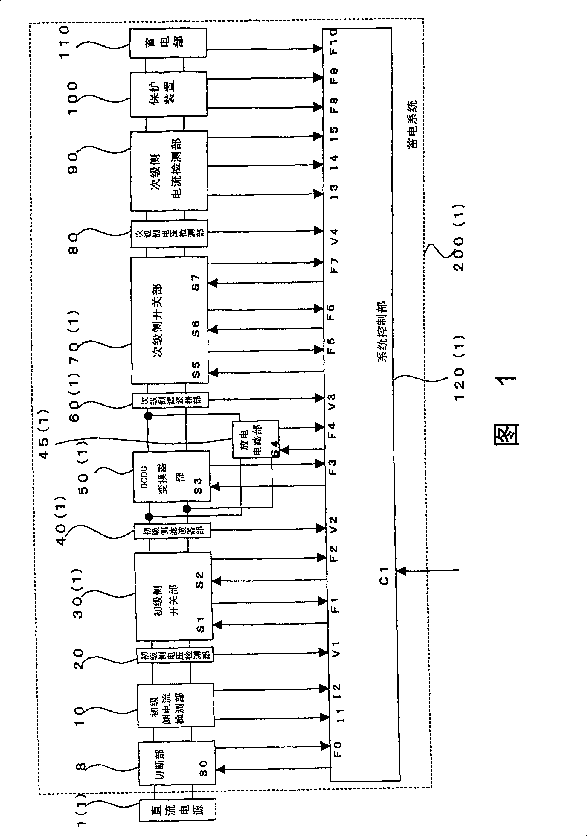
[0045] FIG. 1 is a diagram showing a configuration example of an electric storage system according to Embodiment 1 of the present invention.

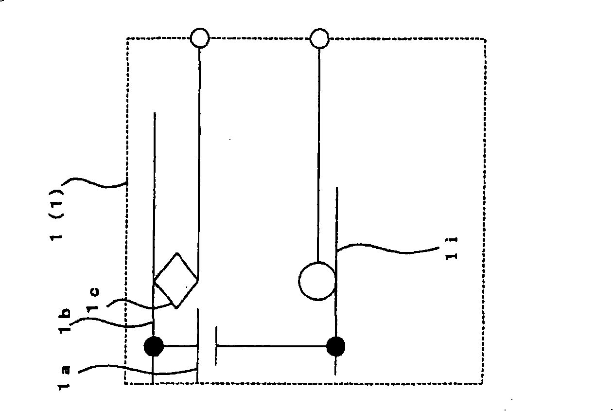
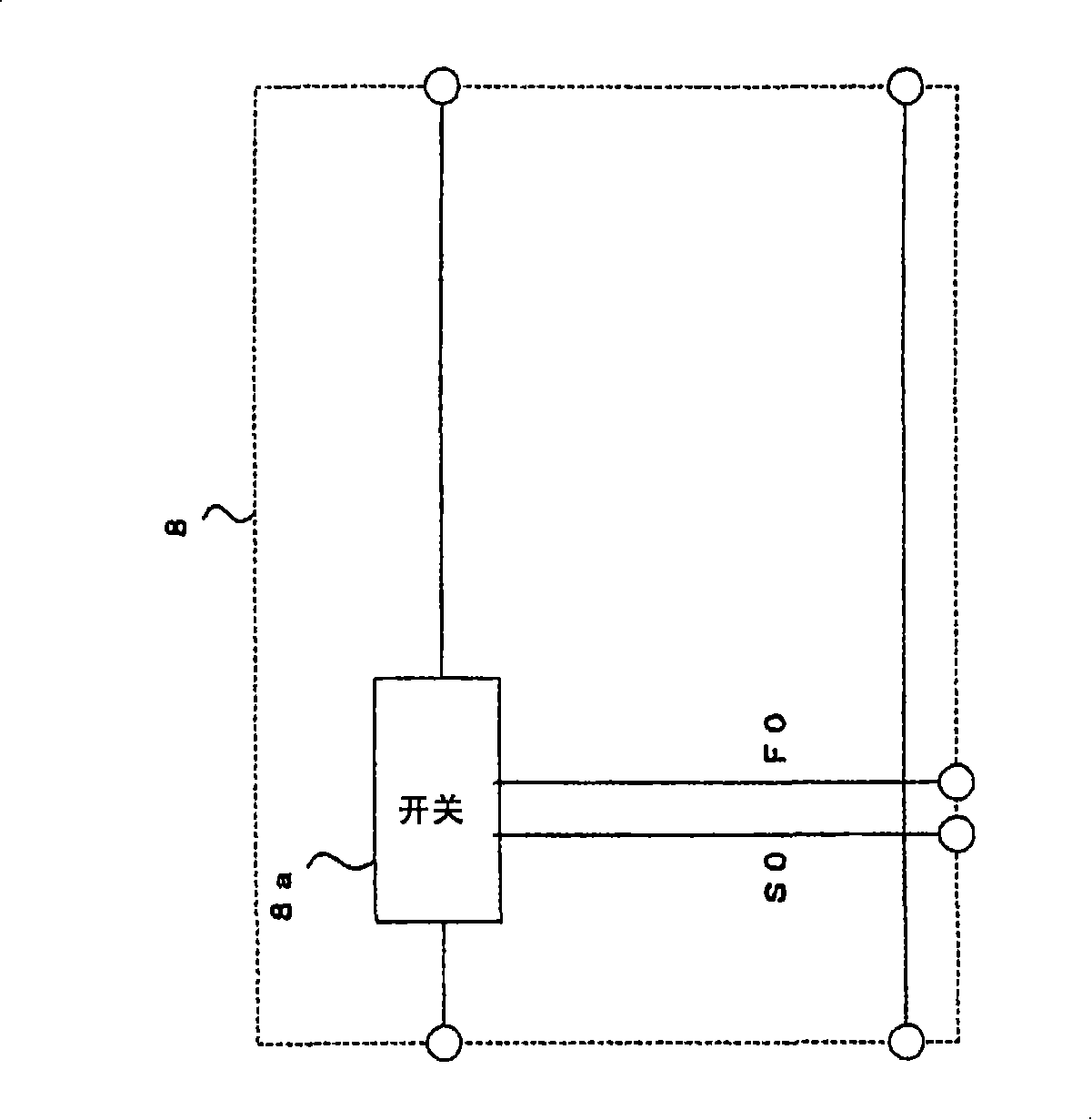
[0046] As shown in FIG. 1 , as a configuration in which the DC power supply 1 ( 1 ) is connected to the power storage system 200 ( 1 ), the power storage system 200 ( 1 ) includes: a cut-off unit 8 having a current cut-off unit; The primary-side current detection unit 10 that detects the current of the primary-side main circuit, the primary-side voltage detection unit 20 that detects the voltage of the primary-side main circuit that is located after the primary-side current detection unit 10 , and the primary-side voltage detection unit 20 that detects the voltage of the primary-side main circuit The primary-side switch section 30(1) that switches the primary-side main circuit on and off, and the primary-side filter section that is located after the primary-side switch section 30(1) and suppresses higher harmonics of the primary-side mai...

Embodiment approach 2

[0290] 18 is a diagram showing a configuration example of an electric storage system according to Embodiment 2 of the present invention.

[0291] Embodiment 2 is a modification based on the composition example of Embodiment 1. Therefore, the same components as those in Embodiment 1 will be assigned the same reference numerals below, and their description will be omitted. Only the different parts will be described.

[0292] As shown in FIG. 18 , a DC power supply 1 ( 2 ) is arranged instead of the DC power supply 1 ( 1 ), and is input to the power storage system 200 ( 2 ).

[0293] The power storage system 200(2) is configured by disposing a primary side filter unit 40(2) instead of the primary side filter unit 40(1).

[0294] FIG. 19 is a diagram showing a configuration example of a DC power supply 1 ( 2 ) according to Embodiment 2 of the present invention.

[0295] As shown in Fig. 19, the DC power supply 1 (2) is the voltage across a capacitor 1f of a circuit composed of a ...

Embodiment approach 3

[0301] 21 is a diagram showing a configuration example of an electric storage system according to Embodiment 3 of the present invention.

[0302] Embodiment 3 is a modification based on the composition example of Embodiment 1. Therefore, the same components as those of Embodiment 1 will be assigned the same reference numerals below, and their description will be omitted. Only the different parts will be described.

[0303] As shown in FIG. 21 , power storage system 200(3) includes discharge circuit 45(2) instead of discharge circuit unit 45(1), and system control unit 120(3) instead of system control unit 12(1).

[0304] The system control unit 120(3) is configured to output the primary side discharge command S41 and the secondary side discharge command S42 to the discharge circuit unit 45(2), and input state signals F41 and F42 from the discharge circuit unit 45(2).

[0305] FIG. 22 is a diagram showing a configuration example of a discharge circuit unit 45 ( 2 ) according to...


PUM


Abstract

To provide a power storage system wherein the activation, operation and stoppage, which are important and essential during the practice of the power storage system, can be performed with reliability and wherein any kinds of extraordinary states can be appropriately dealt with. A power storage system wherein a DC / DC converter part adjusts a DC power from a DC power supply to a predetermined voltage and a predetermined current, which are stored in a power storage part. The power storage system comprises, on the DC power supply source side of the DC / DC converter part (the primary side), a primary side current detecting part, a primary side voltage detecting part, a primary side switch part and a primary side filter part and also comprises, on the power storage part side of the DC / DC converter part (the secondary side), a secondary side filter part, a secondary side switch part, a secondary side voltage detecting part and a secondary side current detecting part. A system control part, which receives an externally given operation command and also receives signals from parts such as the primary side current detecting part and primary side voltage detecting part, performs on / off controls of at least the primary side switch part, DC / DC converter part and secondary side switch part.

Description

technical field [0001] The present invention relates to a power storage system that stores DC power and charges and discharges it, and can be used, for example, in trains and the like. Background technique [0002] In recent years, it is known that a power storage system using a power storage device such as a secondary battery or an electric double-layer capacitor is combined with a drive control inverter mounted on a train and a power supply device installed in a ground substation, etc., to convert the vehicle The surplus regenerative power generated during braking is stored in the power storage device, and the stored power is used when the vehicle accelerates or the line voltage drops, so that the kinetic energy of the vehicle can be effectively used (for example, refer to Patent Document 1 and Patent Document 2) [0003] Patent Document 1: JP 2003-199354 [0004] Patent Document 2: JP 2005-206111 [0005] When the power storage system is actually used, how to configure ...

Claims


Application Information

Patent Timeline
Patent Type & Authority Applications(China)
IPC IPC(8): H02J7/00H02H7/12
CPCB60L2200/26Y02T10/7066B60L2260/165H02J2007/0059H02J7/0029B60L2210/10Y02T10/7216B60L2240/525H02J7/0052H02H7/1213Y02T10/7005B60L11/1868B60L58/20H02J2207/20H02H3/32H02H3/33Y02T10/70Y02T10/72H02J7/00302H02J7/00309H02J7/00306H02J7/00
Inventor 北中英俊
Owner NEXGEN CONTROL SYST LLC
Why Eureka
Try Eureka