Artificial snowing device

A staggered arrangement and scraper technology, applied in the field of indoor environment simulation, can solve the problems of inability to control the speed of snowfall, unable to form snowflakes, occupying a large space, etc., to achieve good snowfall stability, reduce accumulation, and improve the effect of snow scraping Effect

Active Publication Date: 2008-08-13
GREE ELECTRIC APPLIANCES INC
View PDF2 Cites 11 Cited by
  • Summary
  • Abstract
  • Description
  • Claims
  • Application Information

AI Technical Summary

Problems solved by technology

[0003] 1. Spray (water) snowfall method: This method is to frost on the surface of the contact object (such as the surface of the equipment, the ground, etc.), and the visual effect of natural snow will be obtained after a long time at low temperature, and the form of water mist in the air , and the properties of natural snow are quite different, and it is difficult to simulate the effect of moderate snow and heavy snow;
[0004] 2. Cooler frost scraping and snowfall method: as in Chinese patent 93244386.9, the blast pipe blows moist air to the surface of the rotating body, so that the moisture in the air quickly condenses into snowflakes on the surface of the rotating body, and is scraped neatly by the groove seat , and then scraped off with a scraper, and the flow air generated by the rotation of the fan sends the snowflakes out; the snow produced by this method has a better visual effect, but the cost is high, the space is large, and the reliability of the equipment is poor;
This method is easy to control the amount of snowfall, but what falls is ice debris, which is far from the nature of snow
[0006] It can be seen that in the existing snowfall devices, either the speed of snowfall cannot be controlled, or the snowflakes with realistic shapes cannot be formed, that is, the existing snowfall devices cannot form the visual effects and properties of realistic natural snow.

Method used


Image

  • Artificial snowing device
  • Artificial snowing device
  • Artificial snowing device

Examples


Embodiment 1

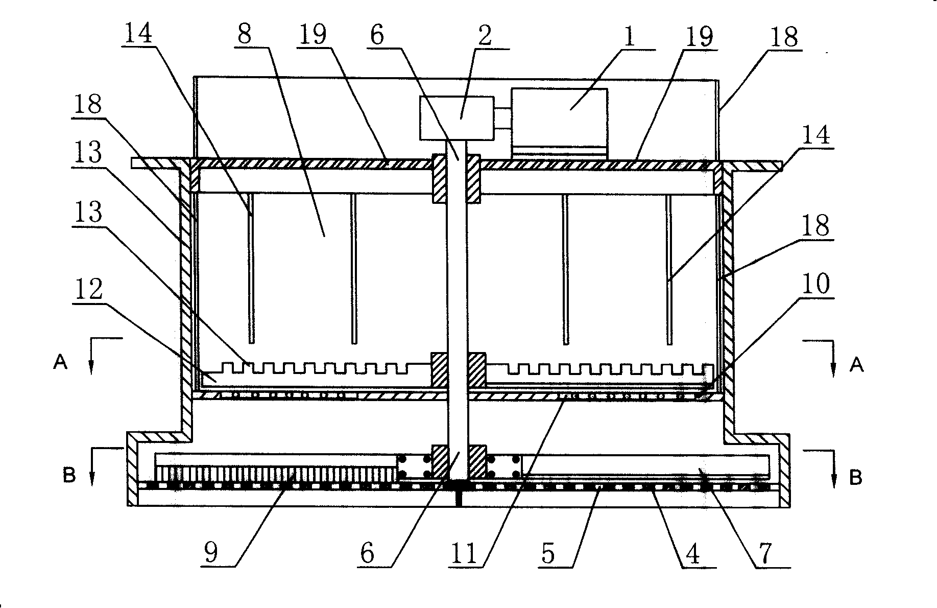
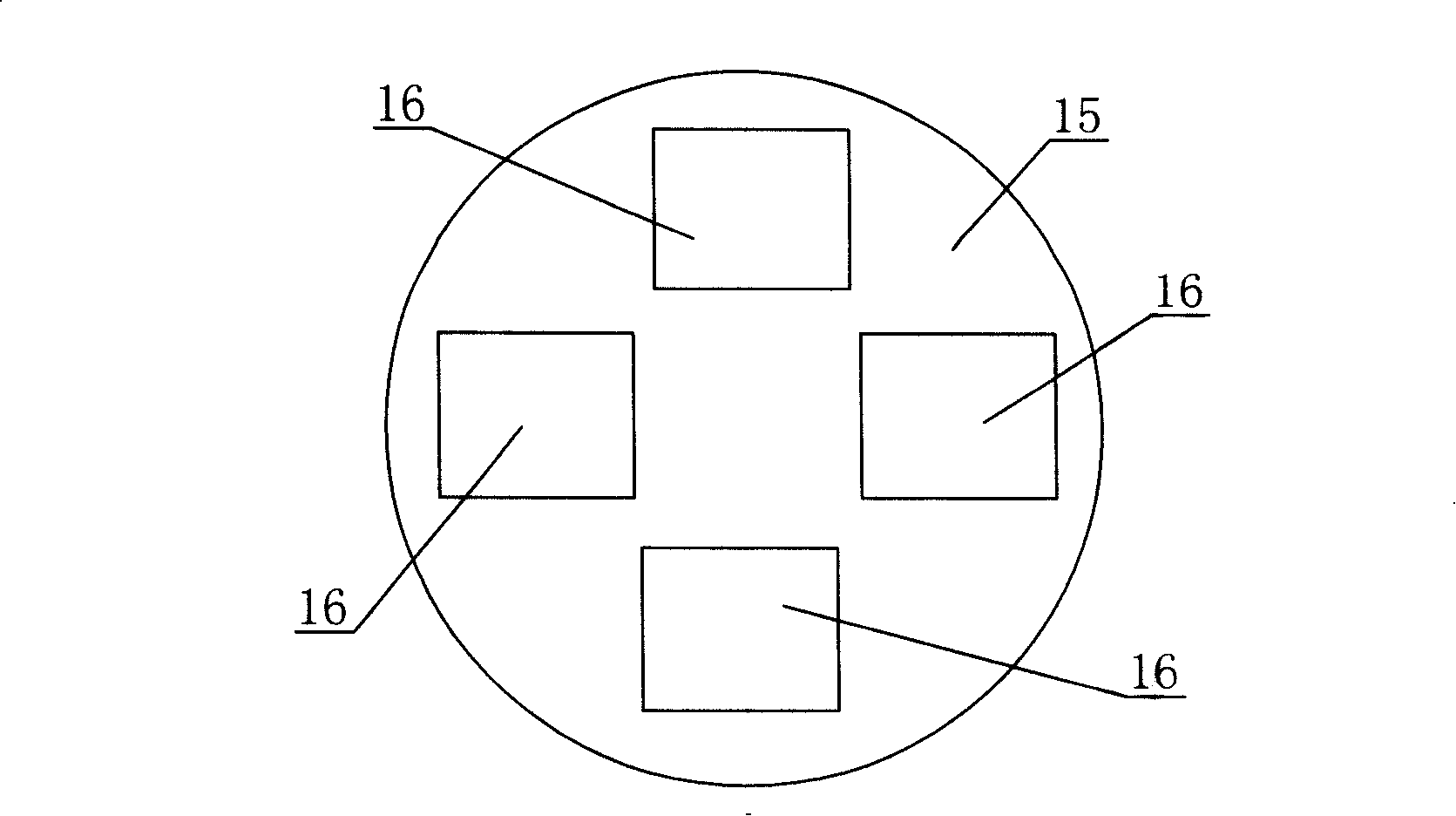
[0039] See Figure 1 to Figure 4 , artificial snowfall device, box body 3 is provided with crossbeam 19, and the upper end of power mechanism 1, reduction box 2 and rotating shaft 6 is all connected on the crossbeam 19, and power mechanism 1 is connected with rotating shaft 6 by reduction box 2 and drives rotating shaft 6 to rotate, The bottom of the box body 3 is an orifice 4 with a snow hole 5, the rotating shaft 6 is perpendicular to the orifice 4, and a scraper 7 is arranged on the top of the orifice 4, which is in contact with the rotating shaft 6. connected to; the top of the orifice plate 4 is also provided with a brush 9 in contact with it, and the brush 9 is connected with the rotating shaft 6 in the circumferential direction; in the box 3, above the scraper 7 is provided with a partition 10, the partition On the 10, there is a snow-draining hole 11 (on the dividing plate 15, a dividing plate hole 16 is provided, and on the dividing plate 15, the dividing plate hole 1...

Embodiment 2

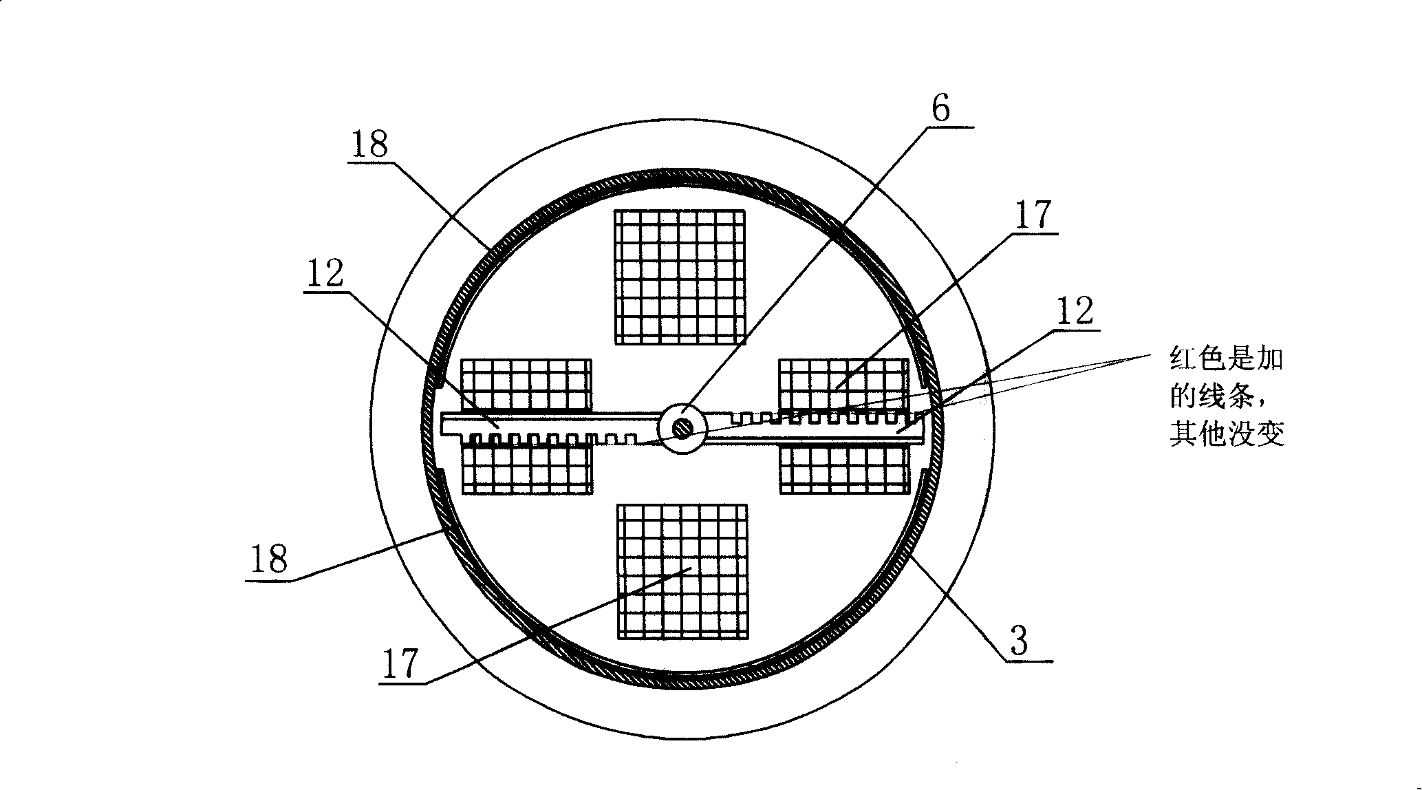
[0043] See Figure 5 The difference between the present embodiment and the first embodiment is that the interlayer 10 is an elastic partition net as a whole, and the snow dredging holes 11 are the mesh holes on the partition net; Four horizontal steel bars are formed; the box body 3 is cylindrical and the diameters of its upper and lower parts are equal to become a straight cylinder, and the diameters of the scraper 7 and the upper scraper 12 are also equal. The principle of this embodiment is the same as that of Embodiment 1, and will not be repeated here.


PUM


Abstract

Disclosed is an artificial snow apparatus, a rotary shaft being rotated by a dynamic mechanism and vertical relative to an orifice plate that is positioned on the bottom of the case body and has orifices allowing snow to pass through. A scraper contacting and working with the orifice plate is circumferentially connected to the rotary shaft and arranged in the upper side of the orifice plate, with space in the case body for storing snow. The invention is capable of controlling snow speed with the appearance of artificial snow more close to natural snow.

Description

technical field [0001] The invention belongs to the field of indoor environment simulation and relates to an artificial snowfall device. Background technique [0002] In scene simulation and experimental environment simulation, artificial snowfall is often used, and the existing artificial snowfall devices often use the following three methods: [0003] 1. Spray (water) snowfall method: This method is to frost on the surface of the contact object (such as the surface of the equipment, the ground, etc.), and the visual effect of natural snow will be obtained after a long time at low temperature, and the form of water mist in the air , and the properties of natural snow are quite different, and it is difficult to simulate the effect of moderate snow and heavy snow; [0004] 2. Cooler frost scraping and snowfall method: as in Chinese patent 93244386.9, the blast pipe blows moist air to the surface of the rotating body, so that the moisture in the air quickly condenses into sno...

Claims


Application Information

Patent Timeline
Patent Type & Authority Applications(China)
IPC IPC(8): F25C3/04
Inventor 张辉王彤田云吕剑明
Owner GREE ELECTRIC APPLIANCES INC
Why Eureka
Try Eureka