Radial double-flow turbine

A steam turbine and two-flow technology, applied in the field of steam turbines, can solve the problems of generating axial force and easily reducing efficiency, and achieve the effects of small energy loss, significant energy saving effect, and convenient maintenance and repair.

Inactive Publication Date: 2011-01-19
程建平 +1
View PDF1 Cites 0 Cited by
  • Summary
  • Abstract
  • Description
  • Claims
  • Application Information

AI Technical Summary

Problems solved by technology

[0004] The present invention solves the disadvantages in the prior art that the steam turbine generates axial force when doing work, which easily reduces the efficiency, and provides a radial double-flow steam turbine that can significantly reduce the axial force and effectively use energy to do work

Method used


Image

  • Radial double-flow turbine
  • Radial double-flow turbine
  • Radial double-flow turbine

Examples


Embodiment

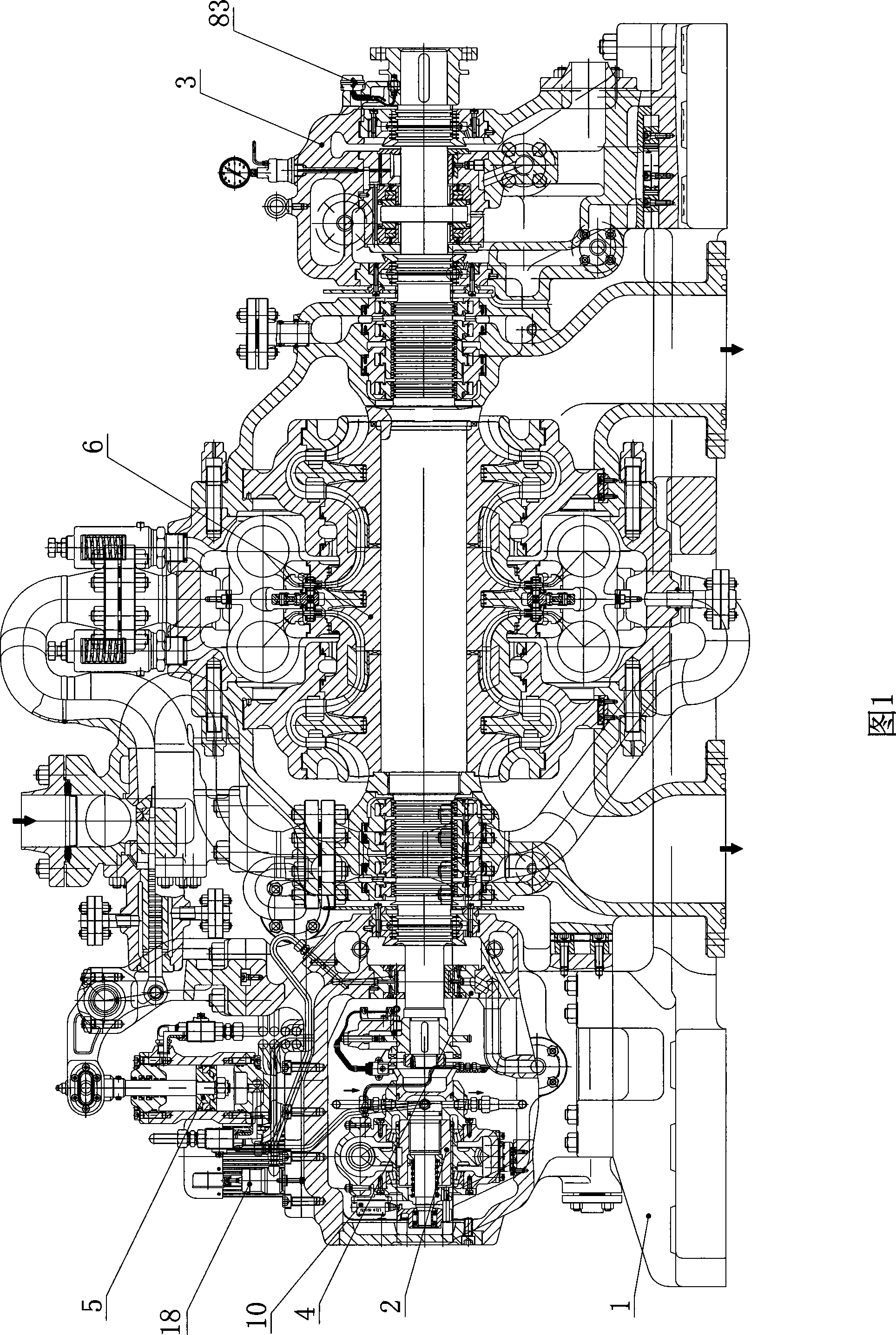
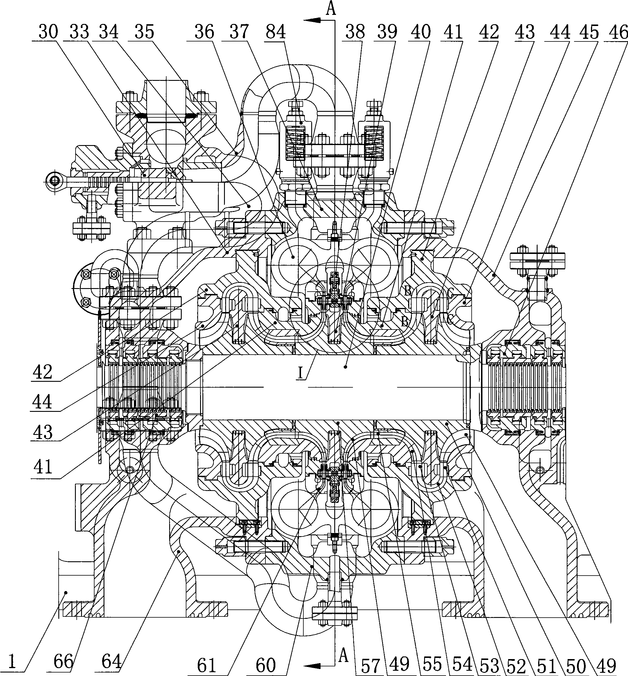
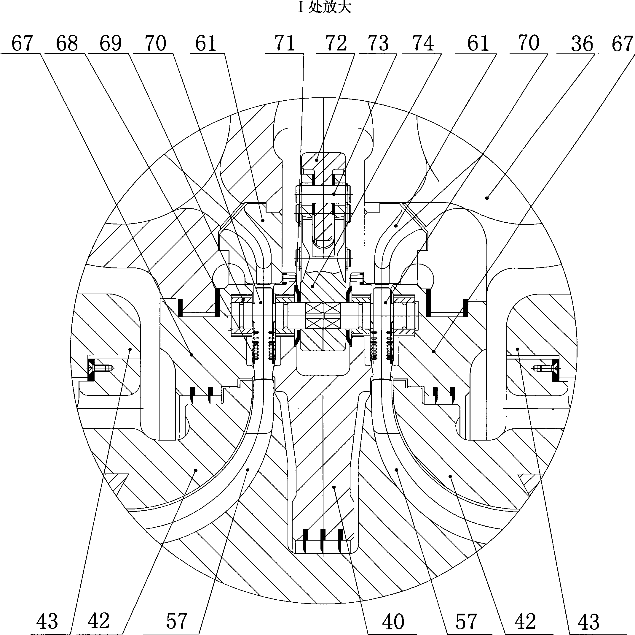
[0046] Embodiment: Radial double-flow steam turbine (referring to appendix figure 1 ) includes a base 1, a front bearing box 2 and a rear bearing box 3 arranged on the base and an adjusting actuator 5 arranged on the top of the front bearing box, a steam turbine body 6 is arranged between the front bearing box and the rear bearing box, and the steam turbine body A main shaft 40 is provided, and the main shaft is connected to the front bearing box and the rear bearing box. There is a double-row centripetal integral impeller 57 in the middle of the main shaft, and there is a centrifugal integral impeller 50 on both sides of the double-row centripetal integral impeller. , the main shaft and the integral impellers adopt an integral structure, and the integral impellers are arranged with equal diameters (see attached Figure 10 ).

[0047] Front bearing box (see attached Figure 18 attached Figure 19 ) consists of a set of overspeed protection device, a bevel gearbox, a reducer...


PUM


Abstract

The invention relates to a steam turbine, in particular to a radial direction double flow type steam turbine which can effectively reduce axial force and use steam flow energy as much as possible. Double rows of centripetal integral impellers are arranged at the center of a live spindle, centrifugal integral impellers are arranged at two sides. The integral impellers do work when steam flow carries out centripetal movement to push the spindle to rotate, and do work again in the centrifugal stage to push the spindle to rotate after the angular transformation, and enter the next circulation. The structure can counteract the generated axial force, reduce the structure, use the centrifugal energy, and improve the efficiency.

Description

technical field [0001] The invention relates to a steam turbine, especially a radial double-flow steam turbine capable of offsetting generated axial force and utilizing the enthalpy drop of heat energy of steam flow to perform work. Background technique [0002] At present, the traditional steam turbines that have been widely used in industrial drives are all blade and impeller assembly steam turbines, including condensing steam, extraction steam condensing, back pressure, extraction back pressure and other structures, and their structural principles are the same. It is an axial flow type, and the rotor can be divided into single-stage and multi-stage structures according to requirements, relying on the expansion of the working fluid to do work, including steam inlet chamber, nozzle group, blade, impeller, main shaft, stator, exhaust chamber, etc. Low thermal efficiency, high energy consumption, complex structure, high requirements and difficulty in blade processing, long pr...

Claims


Application Information

Patent Timeline
Patent Type & Authority Patents(China)
IPC IPC(8): F01D1/06F01D5/04F01D5/14F01D9/02F01D17/14
Inventor 程建平郑群
Owner 程建平
Why Eureka
Try Eureka