Power tool

A power tool and power source technology, applied in the direction of manufacturing tools, manual planers, portable mobile devices, etc., can solve the problems that debris cannot be completely discharged, electric planing is easy to block chips, and chip removal efficiency is low, so as to achieve thorough chip removal , It is not easy to block chips, and the effect of high chip removal efficiency

Inactive Publication Date: 2008-12-31
POSITEC POWER TOOLS (SUZHOU) CO LTD
View PDF1 Cites 7 Cited by
  • Summary
  • Abstract
  • Description
  • Claims
  • Application Information

AI Technical Summary

Problems solved by technology

[0005] The air outlet of the hand-held electric planer is close to the connecting end of the reversing plate and the chip removal valve. The airflow generated by the rotation of the fan enters a cavity of the chip removal valve through the air outlet along the direction perpendicular to the axis of the chip removal valve. The airflow with debris enters the cavity along the direction perpendicular to the airflow generated by the fan. Part of the two airflows cancel each other at the end of the cavity, and the debris at the end cannot be completely discharged, so the efficiency of debris removal is relatively high. Low, the electric planer is easy to block chips during work

Method used


Image

  • Power tool
  • Power tool
  • Power tool

Examples


Embodiment Construction

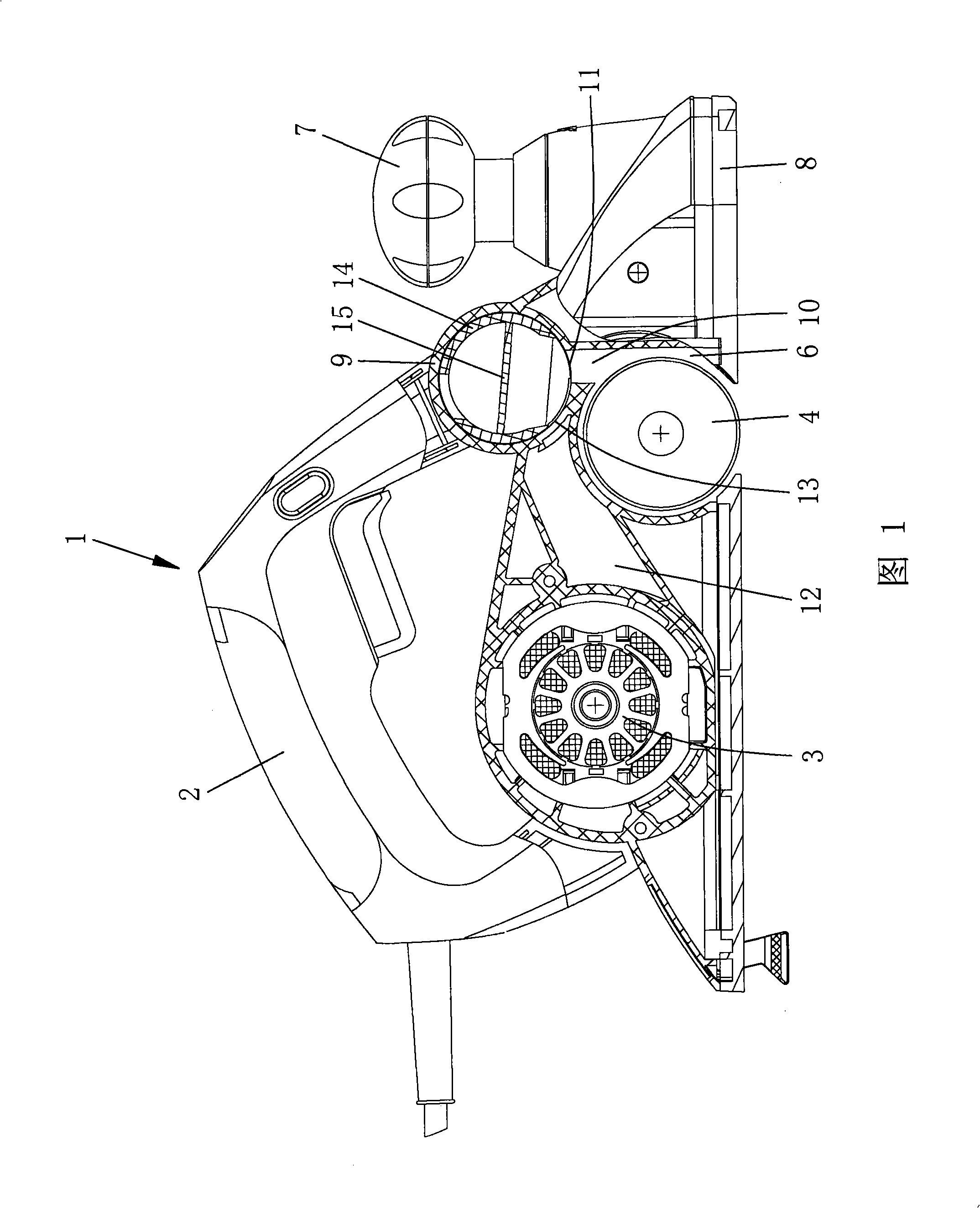
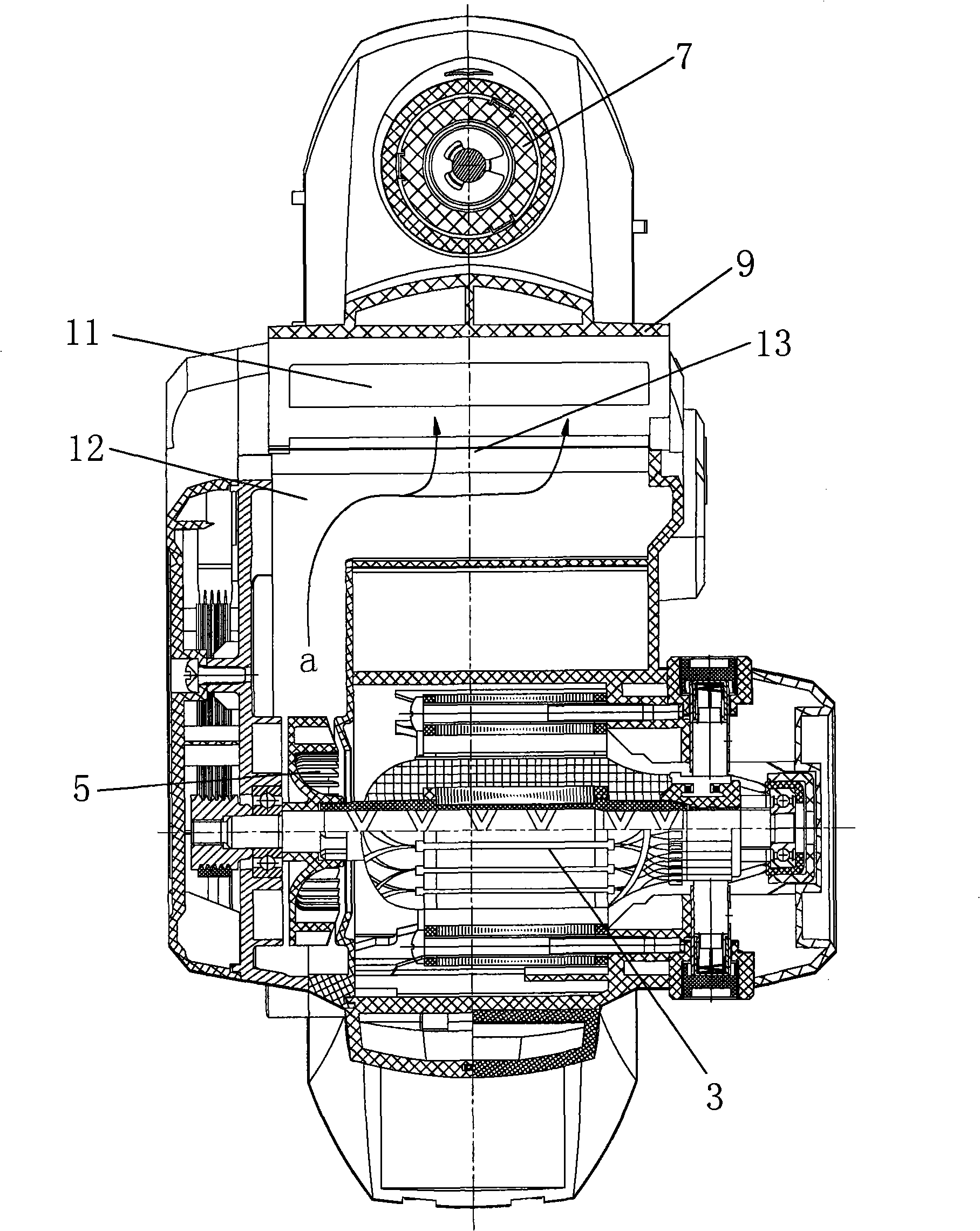
[0032] See Figure 1, figure 2 As shown, a hand-held electric planer has a housing 1, a main handle 2 fixedly connected to the housing 1, a power source 3 accommodated in the housing 1, and a fan 5 connected to the power source 3. The planer 4 driven by the power source 3 is arranged in parallel with the power source 3 .

[0033] The casing 1 has a cylindrical first receiving chamber 6 extending transversely, and the planer 4 is disposed in the first receiving chamber 6 . An adjustable sub-handle 7 is provided near the front of the housing 1, and the sub-handle 7 is used to adjust the height of the bottom plate 8 so as to adjust the cutting depth of the electric planer.

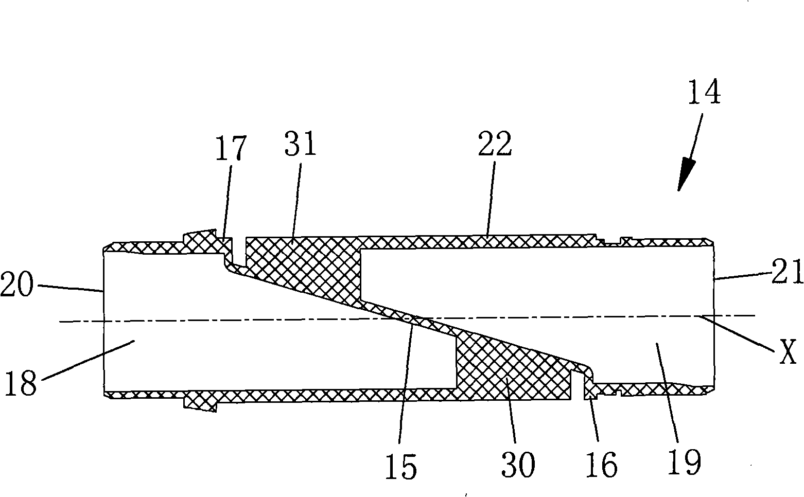
[0034] The casing 1 is located above the first receiving chamber 6 and is provided with a laterally extending tubular second receiving chamber 9 . A chip discharge duct 10 is connected between the first storage cavity 6 and the second storage cavity 9 , and the chip discharge channel 10 has a chip discharge ...


PUM


Abstract

The invention discloses a power tool which comprises a shell, a power source arranged in the shell, a fan connected with the power source and a tubular chip removal valve arranged on the shell; a reversing plate is arranged in the chip removal valve, air inlets are arranged on the tube walls of the chip removal valve at the two sides of the reversing plate, the airflow generated by rotation of the fan enters the chip removal valve from the air inlets, a splitter plate is arranged on the reversing plate near the air inlets, the splitter plate divides the airflow entering the chip removal valve into at least two parts, one part of the airflow is used for reversing the chip entering the chip removal valve, and another part of the airflow is used for blowing chip, therefore, the chip does not accumulate in the chip removal valve, chip removal is thorough and chip removal efficiency is high, and the power tool is not easy to be blocked by the chip in the process of operation.

Description

technical field [0001] The invention relates to a power tool, in particular to a hand-held electric planer with a chip removal valve. Background technique [0002] Hand-held electric planers are widely used in the field of woodworking. [0003] A traditional hand-held electric planer has a housing in which a rotatable planer driven by a motor and a fan connected to the motor are supported. The pipe has two nozzles, one nozzle is set as an air inlet, and the other nozzle is configured as a chip discharge port, and a chip discharge port is provided on the tube wall of the chip discharge pipe close to the planer. The airflow generated by the rotation of the fan enters from the air inlet of the chip discharge pipe, and the debris entering the chip discharge pipe from the chip discharge port is discharged from the chip discharge port. Since the chip discharge pipe is integrally formed on the housing, the chips can only be discharged from the left or right side of the electric p...

Claims


Application Information

Patent Timeline
Patent Type & Authority Applications(China)
IPC IPC(8): B25F5/00B23Q11/00B27C1/10B23D9/00
Inventor 胡方坤
Owner POSITEC POWER TOOLS (SUZHOU) CO LTD
Why Eureka
Try Eureka