High-temperature flue gas quenching device

A high-temperature flue gas and flue gas technology, applied in the field of cooling for industrial production, can solve the problems of increased flue gas flow, acetylene quality impact, energy waste, etc., and achieve the effect of increasing the contact area and good fluidity

Pending Publication Date: 2018-09-14
北京宏帆态金节能科技有限公司
View PDF6 Cites 3 Cited by
  • Summary
  • Abstract
  • Description
  • Claims
  • Application Information

AI Technical Summary

Problems solved by technology

[0004] 1. First of all, a large amount of quenched water injected into water vapor causes changes in the components of the flue gas, causing a sudden increase in the flue gas flow rate, which not only affects the quality of acetylene, but also increases the processing pressure of downstream equipment. Corrosion caused by equipment is also more serious;
[0005] 2. Secondly, the water vapor formed by the injected quenching water is finally emptied, and a large amount of latent heat contained in this period cannot be recovered, resulting in a large waste of energy;
[0006] 3. Again, the water consumption caused by this is not a small figure, which increases the production cost of chemical enterprises but cannot produce any positive and beneficial effects

Method used


Image

  • High-temperature flue gas quenching device
  • High-temperature flue gas quenching device
  • High-temperature flue gas quenching device

Examples


Embodiment Construction

[0032] Further detailed explanation through specific implementation mode below:

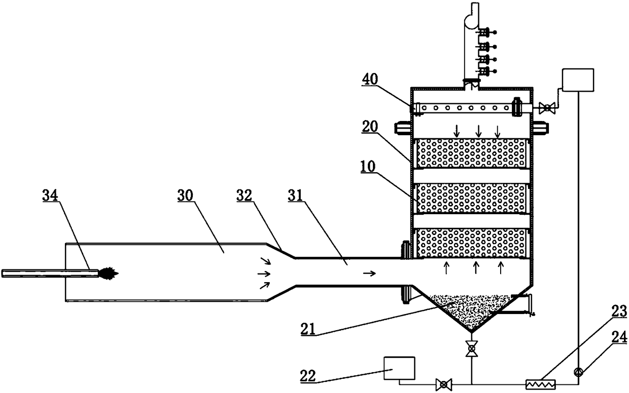
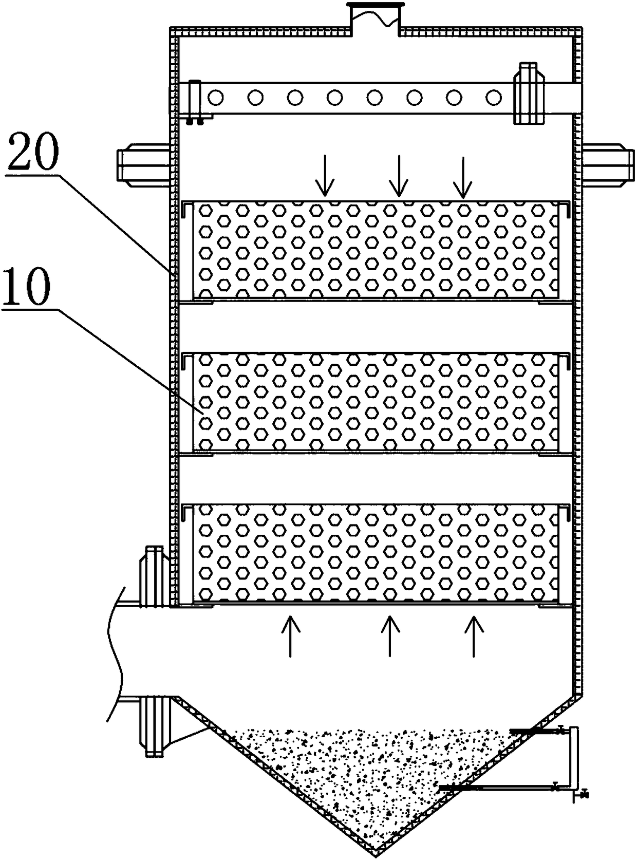
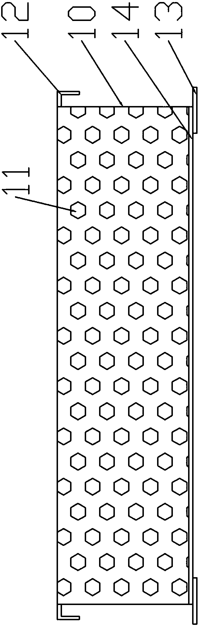
[0033] The reference signs in the accompanying drawings of the specification include: heat sink 10, heat exchange ball 11, outer edge 12, support sheet 13, bottom surface 14, heat exchange furnace 20, liquid accumulation pool 21, liquid storage tank 1 22, heat exchanger 23 , Electromagnetic pump 24, access section 30, contraction section 31, transition section 32, smoke source 34, dispersion disc 40, branch pipe 41, split hole 42, flange plate 43, bracket 44.

[0034] The technical solutions of the present invention will be clearly and completely described below in conjunction with the accompanying drawings. Apparently, the described embodiments are some of the embodiments of the present invention, but not all of them. Based on the embodiments of the present invention, all other embodiments obtained by persons of ordinary skill in the art without making creative efforts belong to the protection s...


PUM

PropertyMeasurementUnit
diameteraaaaaaaaaa
diameteraaaaaaaaaa
melting pointaaaaaaaaaa

Abstract

The invention discloses a high-temperature flue gas quenching device which comprises a flue gas input mechanism and a quenching mechanism arranged in a heat exchange furnace; the flue gas input mechanism comprises a flue which is communicated with a flue gas source and the heat exchange furnace; the quenching mechanism comprises a dispersion disc, a filler unit, a hydrops pool and a circulation unit used for realizing quenching liquid circulation; the circulation unit comprises a heat exchanger which is communicated with the hydrops pool and an electromagnetic pump used for driving the quenching liquid to flow; one end of the electromagnetic pump is communicated with the heat exchanger, and the other end of the electromagnetic pump is communicated with the dispersion disc; the filler unitcomprises heat dissipation drums and heat exchange balls filled in the heat dissipation drums respectively, wherein the top surface and the bottom surface of each heat dissipation drum are arranged ina hollowed manner; the dispersion disc comprises a disc-shaped main body; the disc-shaped main body comprises a main pipe which is communicated with the electromagnetic pump and a plurality of branchpipes which are communicated with the main pipe; and the branch pipes are distributed on the two axial sides of the main pipe respectively. The invention is intended to provide the high-temperature flue gas quenching device capable of effectively lowering the energy consumption and the production cost.

Description

technical field [0001] The invention relates to the field of cooling for industrial production, in particular to a cooling medium dispersion device. Background technique [0002] In industrial production, many fields involve the use of temperature to control the progress of flue gas reactions. [0003] Taking the production of acetylene as an example, the temperature for terminating the reaction is 1300°C, which requires the flue gas temperature to be lowered to an appropriate range in the heat exchange furnace. At present, this process is realized by spraying into quenching water, however, there are following problems in this way: [0004] 1. First of all, a large amount of quenched water injected into water vapor causes changes in the composition of the flue gas, causing a sudden increase in the flue gas flow rate, which not only affects the quality of acetylene, but also increases the processing pressure of downstream equipment. Corrosion caused by equipment is also mor...

Claims


Application Information

Patent Timeline
Patent Type & Authority Applications(China)
IPC IPC(8): F27D17/00
CPCF27D17/004F27D17/008
Inventor 杨帆
Owner 北京宏帆态金节能科技有限公司
Why Eureka
Try Eureka