Push plate type chip removing groove
A chip removal groove and push plate technology, which is applied to metal processing machinery parts, maintenance and safety accessories, metal processing equipment, etc., can solve the problems of difficult maintenance, poor chip removal effect, and high noise, so as to reduce the failure rate, Ease of maintenance, reducing possible effects of entering track grooves
- Summary
- Abstract
- Description
- Claims
- Application Information
AI Technical Summary
Problems solved by technology
Method used
Image

Examples
Embodiment Construction
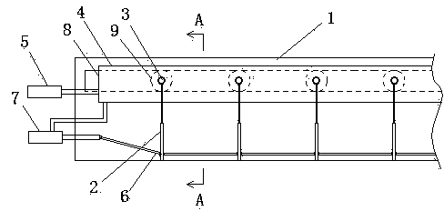
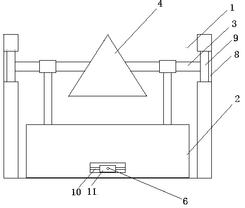
[0024] Such as figure 1 and figure 2 The push plate type chip flute shown includes a groove 1, at least two push plates 2 arranged at intervals, and a main shaft 4. The cross section of the main shaft 4 is triangular, one of the corners is upward; the two sides of the main shaft 4 are respectively connected There is a shaft 3, the outer end of the shaft 3 is connected with a roller 9, the shaft 3 is also rotatably connected with a shaft sleeve, the upper end of the push plate 2 is fixedly connected with a vertical rod, and the upper end of the vertical rod is fixedly connected with the shaft sleeve The outer wall makes the two sides of the push plate 2 respectively face the two ends of the groove 1; the upper part of the two side walls of the groove 1 is respectively provided with a track groove 8 parallel to the groove 1, and the roller 9 is rollingly connected to the track groove 8; the main shaft 4. One end is transmitted with the first hydraulic piston 5, and the second...
PUM
 Abstract
Description
Claims
Application Information