AI technical title is built by Patsnap AI team. It summarizes the technical point description of the patent document.
An occluder, intelligent technology, applied in the direction of special pipes, pipe components, pipes/pipe joints/pipe fittings, etc., to achieve the effect of simple, fast and reliable occlusion operation
Active Publication Date: 2010-06-23
BC P INC CHINA NAT PETROLEUM CORP +1
View PDF0 Cites 1 Cited by
Summary
Abstract
Description
Claims
Application Information
AI Technical Summary
This helps you quickly interpret patents by identifying the three key elements:
Problems solved by technology
Method used
Benefits of technology
Problems solved by technology
[0008] The technical problem to be solved by the present invention is to overcome the deficiencies in the existing pipeline opening, sealing and maintenance technology and technology to provide an in-pipe intelligent occluder, which can realize the in-pipe plugging and unblocking by remote control without losing power, especially It can be applied to the high-pressure plugging in the pipe. The plugging operation is very simple and fast, and has basically no effect on the normal transportation. It can also provide sufficient locking force for the inner wall of the pipe with any obstacles such as straight welds or spiral welds and deformation. Reliable plugging of pipelines of any precision
Method used
Image
Click on the blue label to locate the original text in one second.
Reading with bidirectional positioning of images and text.
Examples
Embodiment approach 1
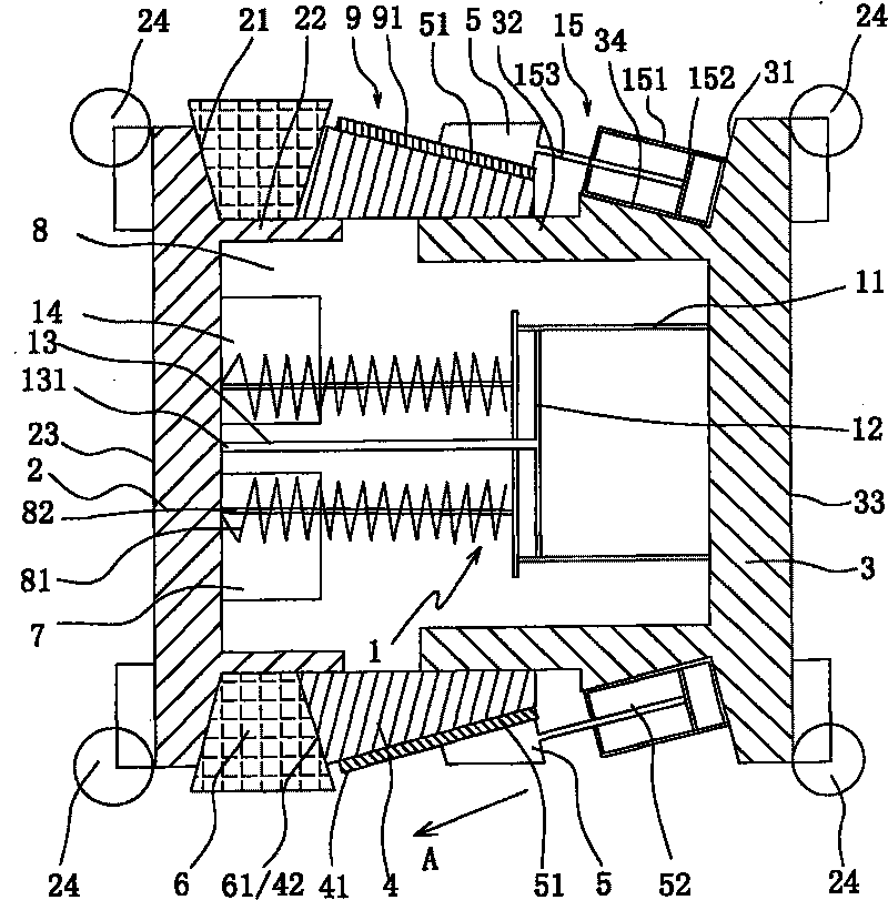
[0027] Such as figure 1 , 2 As shown, a kind of in-pipe intelligent occluder provided by the present invention includes:
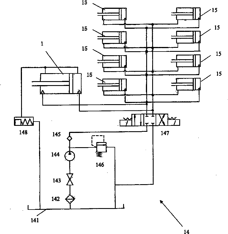
[0028] A main drive cylinder 1, the main drive cylinder 1 has a cylinder body 11, a piston 12 and a piston rod 13 connected with the piston 12, the preferred hydraulic cylinder of the main drive cylinder 1;
[0029] A pressure head 2, connected to the end 131 of the piston rod 13 away from the piston 12;
[0030] An actuator disc 3, connected to the cylinder body 11;
[0031] An extrusion bowl 4, which is slidingly arranged between the pressure bearing head 2 and the actuator disk 3, the extrusion bowl 4 has an inclined sliding cone surface 41 and an extrusion end surface 42;
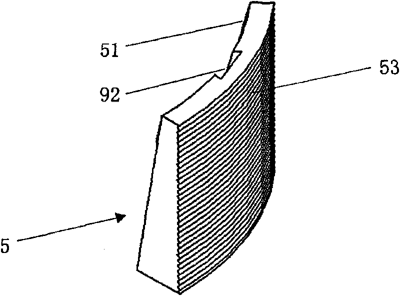
[0032] At least two locking sliders 5, preferably including eight and evenly distributed along the circumferential direction, to ensure that the locking force is balanced, eight locking sliders 5 are respectively connected to eight auxiliary drive cylinders 15, and each auxiliary...
Embodiment approach 2
[0048] Such as Figure 5 As shown, the structure, principle and effect of this embodiment are basically the same as Embodiment 1, and will not be repeated. The difference is that neither the signal transceiver device 7 nor the miniature main hydraulic system 14 is arranged inside the intelligent occluder in the pipe. In the hollow chamber 8, it is hung on the outside of the intelligent occluder in the tube.
[0049] Specifically, a sealing cylinder 70 is hung on the outer end surface 23 of the pressure bearing head 2, the control module 140 of the signal transceiver device 7 and the miniature main hydraulic system 14, the fuel tank 141 of the battery pack 149 and the pressure maintaining circuit, the hydraulic pump 144 and All hydraulic components (not shown in the figure) are arranged in the sealing cylinder 70 . Of course, the sealing cylinder 70 can also be hung on the outer end surface 33 of the actuator disk 3 without limitation. In this case, each support wheel 24 needs...
PUM
Abstract
The invention provides an intraductal intelligent plugging device, which comprises a main drive cylinder, a pressure head, an actuator disk, an extrusion bowl, at least two locking slide blocks, a ring spacer and a signal transceiver device, wherein, the main drive cylinder is provided with a cylinder body, a piston and a piston rod connected with the piston; the pressure head is connected with the end of the piston rod far away from piston; the actuator disk is connected with the cylinder body; the extrusion bowl is arranged between the pressure head and the actuator disk in a sliding way, and the extrusion bowl is provided with a tilted conical slide surface and an extrusion end face; each of the two locking slide blocks is connected with a subsidiary drive cylinder, and each subsidiarydrive cylinder is fixed on the actuator disk; the bottom surface of the locking slide block is matched with the conical slide surface of the extrusion bowl in a sliding way, and the locking slide block performs the locking function in a radial expansion way when sliding upward along the conical slide surface; the ring spacer is arranged between the pressure head and the actuator disk, and is extruded by the extrusion end face of the extrusion bowl to perform the plugging function in a radial expansion way; the signal transceiver device is connected with the intraductal intelligent plugging device to receive control signals to drive the main drive cylinder.
Description
technical field [0001] The present invention relates to a plugging device among plugging tools for pipeline maintenance of water, oil, gas and other media, in particular to a remote-controlled intelligent plugging device in a high-pressure pipe that can self-block and unblock in high-pressure pipes. Background technique [0002] Pipeline transportation is the most economical and reasonable transportation method for oil and gas. By the end of 2006, the total length of my country's long-distance oil and gas pipelines had exceeded 50,000 kilometers, including about 30,000 kilometers of natural gas pipelines, about 15,000 kilometers of crude oil pipelines, and about 5,600 kilometers of refined oil pipelines. At present, a number of oil and gas regional pipeline networks have been formed in my country, including relatively complete regional natural gas pipeline networks in Sichuan-Chongqing, North China and the Yangtze River Delta regions, the main framework of regional natural g...
Claims
Application Information
Patent Timeline
Application Date:The date an application was filed.
Publication Date:The date a patent or application was officially published.
First Publication Date:The earliest publication date of a patent with the same application number.
Issue Date:Publication date of the patent grant document.
PCT Entry Date:The Entry date of PCT National Phase.
Estimated Expiry Date:The statutory expiry date of a patent right according to the Patent Law, and it is the longest term of protection that the patent right can achieve without the termination of the patent right due to other reasons(Term extension factor has been taken into account ).
Invalid Date:Actual expiry date is based on effective date or publication date of legal transaction data of invalid patent.

