

Intelligent plugging device in tube
An occluder, intelligent technology, applied in the direction of special pipes, pipe components, pipes/pipe joints/pipe fittings, etc., to achieve the effect of simple, fast and reliable occlusion operation
- Summary
- Abstract
- Description
- Claims
- Application Information
AI Technical Summary
Problems solved by technology
Method used
Image

Examples
Embodiment approach 1
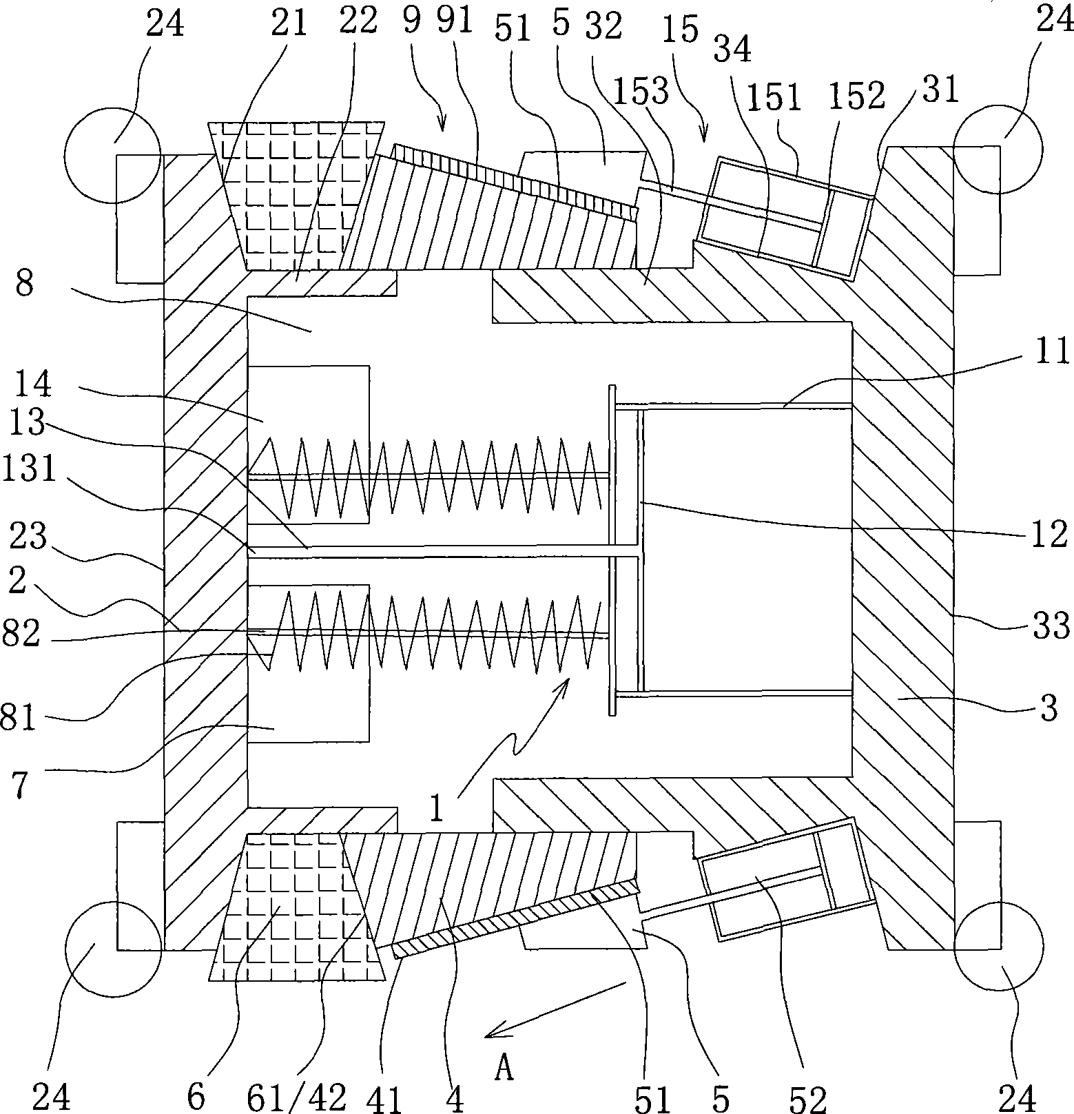
[0027] Such as figure 1 , 2 As shown, a kind of in-pipe intelligent occluder provided by the present invention includes:
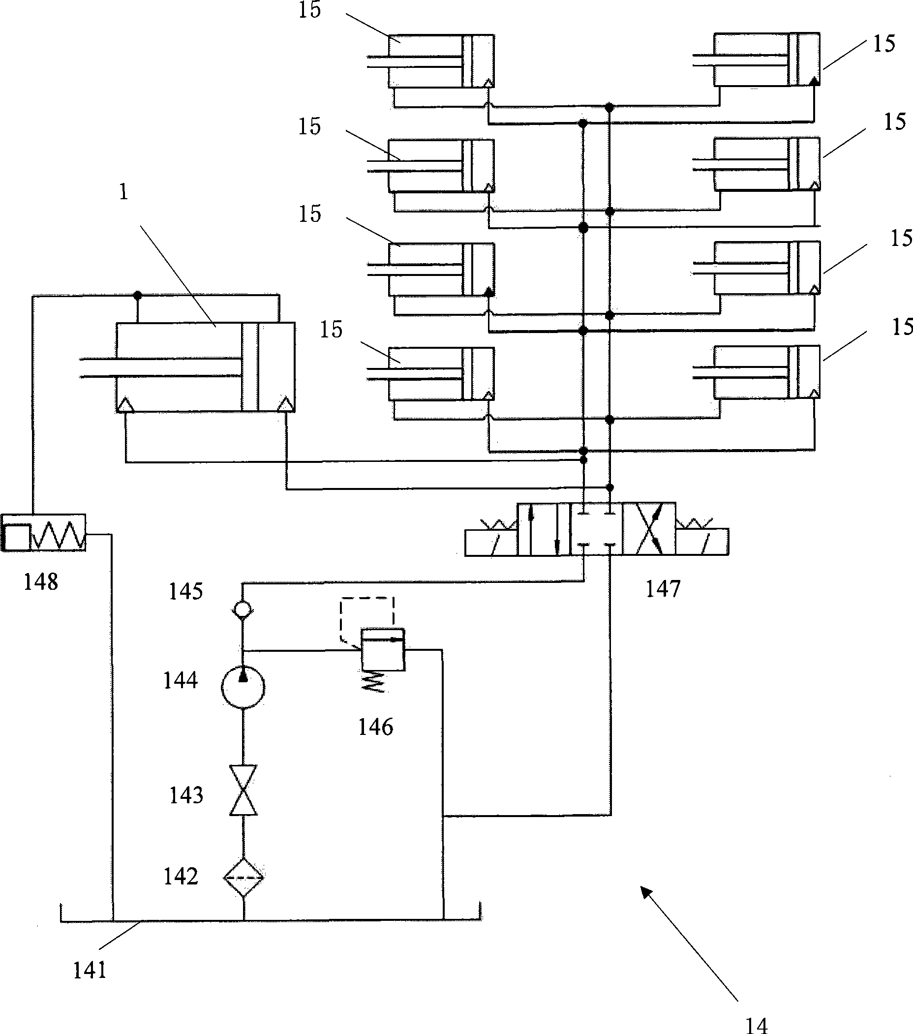
[0028] A main drive cylinder 1, the main drive cylinder 1 has a cylinder body 11, a piston 12 and a piston rod 13 connected with the piston 12, the preferred hydraulic cylinder of the main drive cylinder 1;
[0029] A pressure head 2, connected to the end 131 of the piston rod 13 away from the piston 12;
[0030] An actuator disc 3, connected to the cylinder body 11;
[0031] An extrusion bowl 4, which is slidingly arranged between the pressure bearing head 2 and the actuator disk 3, the extrusion bowl 4 has an inclined sliding cone surface 41 and an extrusion end surface 42;
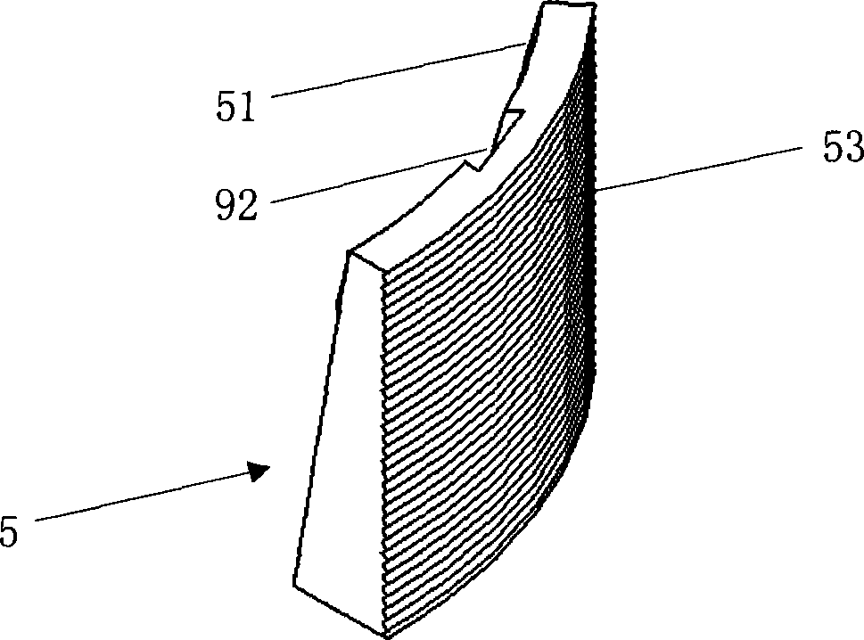
[0032] At least two locking sliders 5, preferably including eight and evenly distributed along the circumferential direction, to ensure that the locking force is balanced, eight locking sliders 5 are respectively connected to eight auxiliary drive cylinders 15, and each auxiliary...
Embodiment approach 2
[0048] As shown in Figure 5, the structure, principle and effect of this embodiment are basically the same as Embodiment 1, and will not be repeated. The difference is that neither the signal transceiver device 7 nor the miniature main hydraulic system 14 is installed in the pipe for intelligent sealing In the hollow chamber 8 inside the device, but connected to the outside of the intelligent occluder in the tube.
[0049] Specifically, a sealing cylinder 70 is hung on the outer end surface 23 of the pressure bearing head 2, the control module 140 of the signal transceiver device 7 and the miniature main hydraulic system 14, the fuel tank 141 of the battery pack 149 and the pressure maintaining circuit, the hydraulic pump 144 and All hydraulic components (not shown in the figure) are arranged in the sealing cylinder 70 . Of course, the sealing cylinder 70 can also be hung on the outer end surface 33 of the actuator disk 3 without limitation. In this case, each support wheel 24...
PUM
 Abstract
Description
Claims
Application Information