
Plugging device

A technology for sealing devices and mounting holes, which is applied in the direction of engine sealing devices, engine components, machines/engines, etc. It can solve the problems of affecting the extrusion effect of the tie rod on the sealing ring, and the easy wear and deformation of the cam part, so as to achieve reliable sealing , Ease of use

Active Publication Date: 2017-01-04
ANHUI JIANGHUAI AUTOMOBILE GRP CORP LTD
View PDF5 Cites 5 Cited by
  • Summary
  • Abstract
  • Description
  • Claims
  • Application Information

AI Technical Summary

Problems solved by technology

[0005] The present invention solves the problem that when the pull rod is driven by the cam part in the prior art, the cam part is easy to wear and deform after long-term use, thereby affecting the extrusion effect of the pull rod on the sealing ring

Method used


Image

  • Plugging device
  • Plugging device
  • Plugging device

Examples


Embodiment Construction

[0028] In order to enable those skilled in the art to better understand the technical solutions of the present invention, the present invention will be further described in detail below in conjunction with the accompanying drawings.

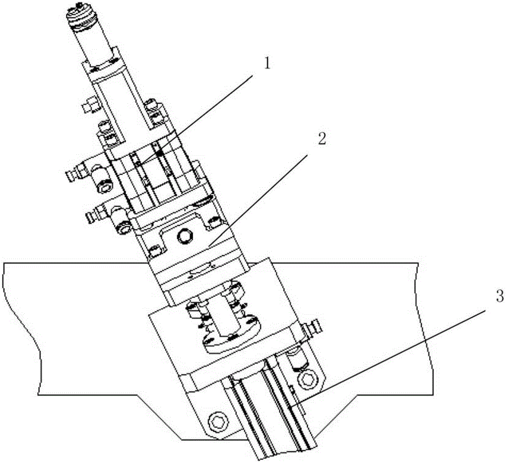
[0029] Such as image 3 As shown, a blocking device provided by the present invention includes a driving mechanism 3 and a blocking mechanism 1 connected to the driving mechanism 3, wherein the driving mechanism is driven by a commonly used cylinder, and the present invention redesigns the blocking mechanism, In order to avoid its damage during long-term use, it is convenient to use.

[0030] Specifically, as Figure 4-6 As shown, in this embodiment, the blocking mechanism 1 specifically includes:

[0031] A cylinder 101, one side of the cylinder 101 is connected with the drive mechanism, the cylinder joint 108 of the cylinder 101 stretches out from the drive mechanism 3, and the cylinder 101 drives the cylinder joint 108 to move telescopically...


PUM


Abstract

The invention discloses a plugging device which comprises a driving mechanism and a plugging mechanism connected with the driving mechanism. The plugging mechanism comprises a cylinder, a support, a guide sleeve and a pull rod, one side of the cylinder is connected with the driving mechanism, a cylinder connector extends out of the driving mechanism in a backing manner, the support is fixed on the cylinder, a guiding hole is formed in one surface of the support far away from the cylinder, one end of the guide sleeve is fixed at the outer edge of the guiding hole, the other end of the guide sleeve extends toward the direction far away from the guiding hole, the bottom end of the pull rod is connected with the cylinder connector, the top end of the pull rod sequentially penetrates the guiding hole and the support and then is connected with a pull block, and an annular projection is arranged on the front side of the pull rod and positioned between the pull block and the guide sleeve. Reliable plugging operations are achieved by the cylinder without manpower, and the plugging device is convenient to use.

Description

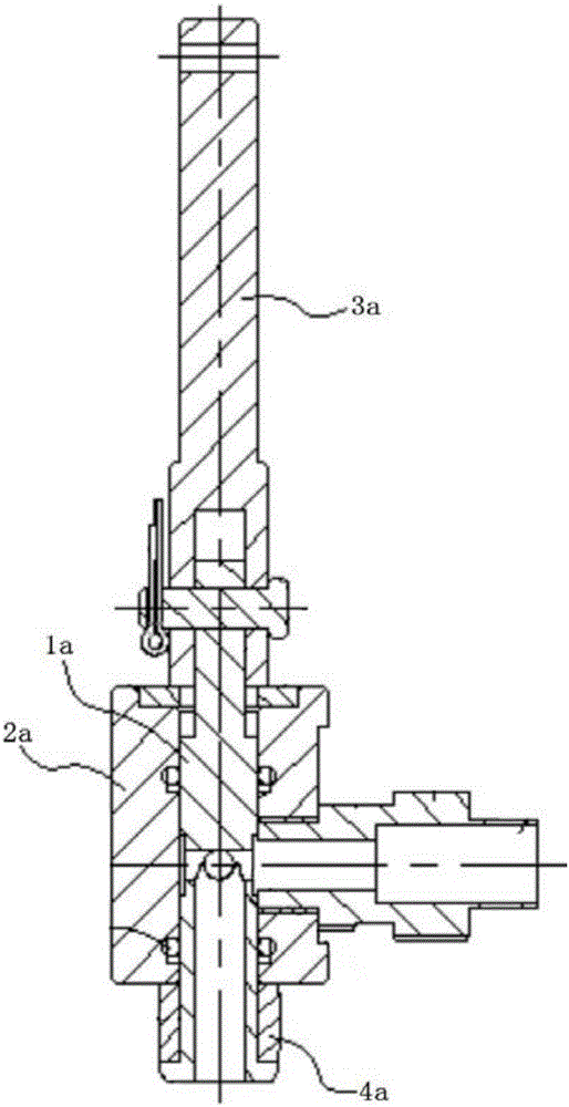
technical field [0001] The invention relates to the field of leak test and detection devices for automobile engine water channels, in particular to a blocking device. Background technique [0002] At present, when the engine waterway is tested for leaks, the water pipe mouth is usually blocked by the end face of the hole to be blocked. The patent application number: 201610028443.0 discloses a sealing device for the hole of the engine oil dipstick, such as figure 1 -2, wherein the sealing mechanism of the sealing device mainly includes a guide sleeve 2a, a pull rod 1a and a handle 3a, wherein the pull rod 1a is installed in the guide sleeve, and its front end is used to fix the sealing end of the sealing ring 4a, and its The rear end is rotatably connected with the cam part 31a of the handle 3a. When in use, the handle 3a is turned, the cam part 31a rotates, and the pull rod 1a moves away from the oil dipstick hole relative to the sleeve 2a. At this time, the sealing sleeve i...

Claims


Application Information

Patent Timeline
IPC IPC(8): F02F11/00F01P11/00F01P11/04G01M3/02
CPCF01P11/00F01P11/04F02F11/00G01M3/02
Inventor 曹金贵
Owner ANHUI JIANGHUAI AUTOMOBILE GRP CORP LTD
Learn More