Gluing cable connector box

A joint box and cable technology, applied in the direction of cable joints, cable terminals, etc., can solve the problems of poor air sealing, inconvenient installation and operation, poor strength, etc., and achieve the effect of wide application range, convenient cable fixing and advanced structure design.

Inactive Publication Date: 2009-04-15
成都华铁电子技术发展有限公司
View PDF0 Cites 13 Cited by
  • Summary
  • Abstract
  • Description
  • Claims
  • Application Information

AI Technical Summary

Problems solved by technology

The cable with this structure is referred to as oil-filled cable. The existing oil-filled cable has poor airtightness, poor strength, and inconvenient installation and operation.

Method used


Image

  • Gluing cable connector box

Examples


Embodiment 1

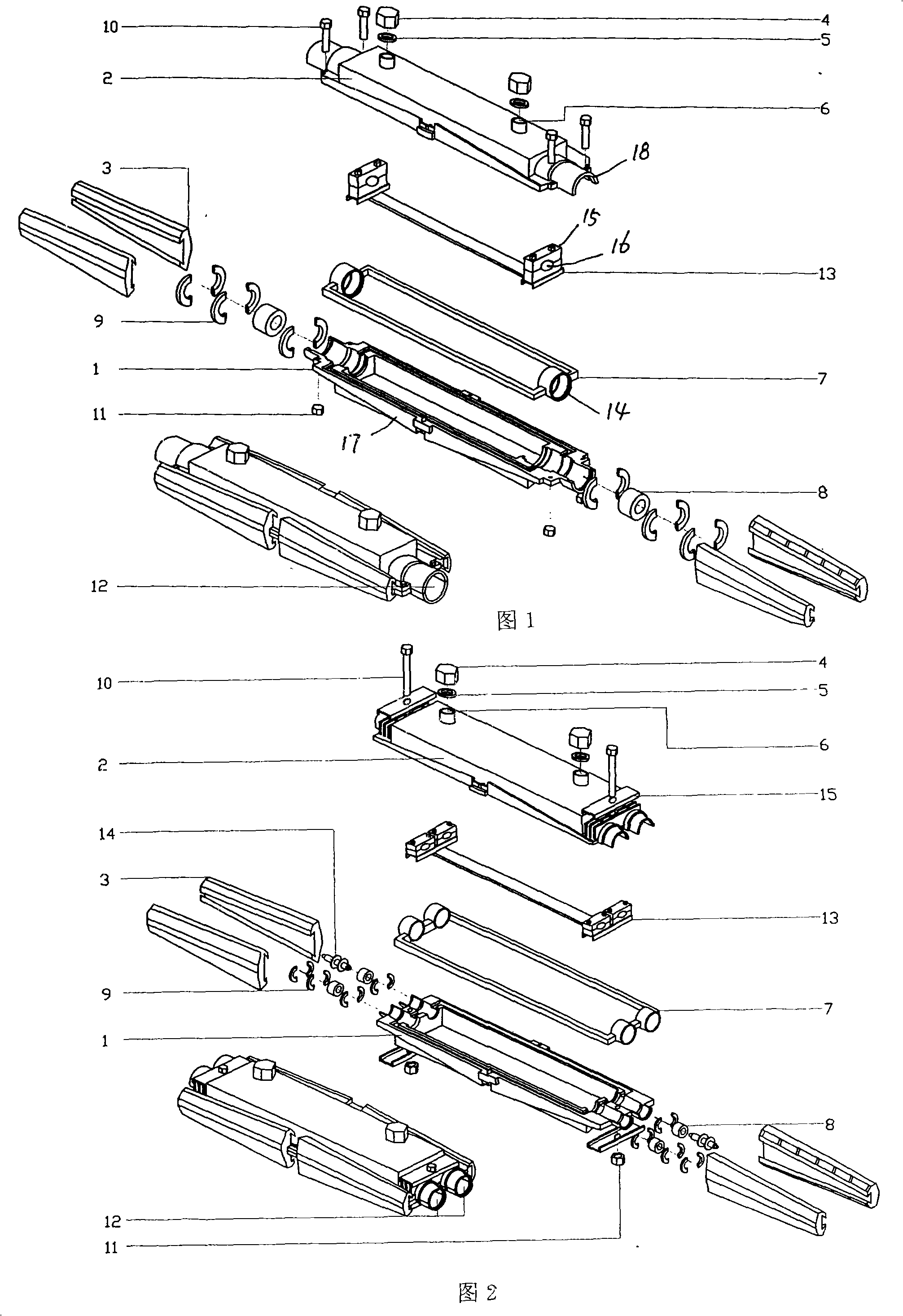
[0023] Example 1: Straight-through Cable Splice Box

[0024] The two ends of the box body 1 and the box cover 2 respectively have a semicircular ring 18 to form a cable inlet 12 . A rubber ring 14 is respectively arranged at both ends of the rectangular sealing ring 7 and is located in the cable inlet 12 . There are two holes 6 on the lid to cooperate with the blocking cover 4, one as a filling hole and the other as an air outlet. There is rubber reducing sleeve 8 in the rubber ring 14, and retaining ring 9 is arranged at the two ends of reducing sleeve. Back-up ring 9 has two broken grooves along the diameter. A support 13 is arranged in the box to be connected with the cable clamp 15.

[0025] During use, the cable ends that have been cleaned up are fixed on the support 13 with screws and cable clamps 15 . The inner diameter of the reducing sleeve 8 is 1mm-1.5mm smaller than the outer diameter of the cable aluminum sheath. The sections of the rubber ring 14 and the redu...

Embodiment 2

[0027] Embodiment 2: branched cable splice box

[0028] Two semicircular rings 18 are respectively arranged at two ends of the box body 1 and the box cover 2 to form two cable inlets 12, and two rubber rings 14 are respectively arranged at the two ends of the rectangular sealing ring 7 to be positioned in the cable inlet, and the rest are the same as in Embodiment 1.


PUM


Abstract

The invention discloses an encapsulated cable closure, and aims at solving the problems of poor air-tightness, poor strength and inconvenient operation of the existing encapsulated cable closures. The encapsulated cable closure consists of a box body (1) and a box cover (2) which are connected with each other, and a connecting device is arranged at the joint; cable inlets (12) at two axial ends of the box consists of symmetrical semicircles (18) which are respectively arranged on the box body and the box cover; a seal groove and a seal ring (7) are in scarf joint with each other at an abutting joint surface of the box body and the box cover; two axial ends of the seal ring (7) are provided with rubber rings (14) which are arranged in the cable inlets (12); and the box cover (2) is provided with at least two holes (6) which are matched with blanking covers (4).

Description

Technical field: [0001] The invention is related to the connecting device of railway oil-filled signal and communication cables. Background technique: [0002] With the development of railways in the direction of high speed, heavy load and high density, a large number of railway signals are equipped with computer interlocking, automatic blocking, station coding and computer detection equipment. In order to improve the reliability of railway signal digital and analog information transmission channels, a large number of railway inner shielded digital signal cables are currently used. In addition to forming a shield for each group of core wires, this kind of signal cable adopts a structure in which insulating ointment fills the metal sleeve in order to ensure insulation performance. In order to reduce maintenance costs, railway communication cables also use a large number of insulating grease-filled metal sleeve structures from traditional inflatable cables. The cable of this...

Claims


Application Information

Patent Timeline
IPC IPC(8): H02G15/06H02G15/10
Inventor 刘新田朱小敏邵兵龙丽林
Owner 成都华铁电子技术发展有限公司
Why Eureka
Try Eureka