
Cable installation adjusting frame for electric power engineering construction

A cable installation and power engineering technology, applied in the direction of electrical components, etc., can solve the problems of cable damage, the installation frame can not adjust the size of the cable turning radius, etc., to achieve the effect of reducing damage, easy to fix the cable, and balanced force

Pending Publication Date: 2022-01-14
中国电建集团河北工程有限公司
View PDF0 Cites 0 Cited by
  • Summary
  • Abstract
  • Description
  • Claims
  • Application Information

AI Technical Summary

Problems solved by technology

[0003] The purpose of the present invention is to provide a cable installation and adjustment frame for electric power engineering construction to solve the problem that the existing installation frame cannot adjust the turning radius according to the thickness of the cable, and the cable is easily damaged when it is bent when installing the cable. question

Method used


Image

  • Cable installation adjusting frame for electric power engineering construction
  • Cable installation adjusting frame for electric power engineering construction
  • Cable installation adjusting frame for electric power engineering construction

Examples


Embodiment 1

[0033] Embodiment 1 Cable installation and adjustment frame for electric power engineering construction

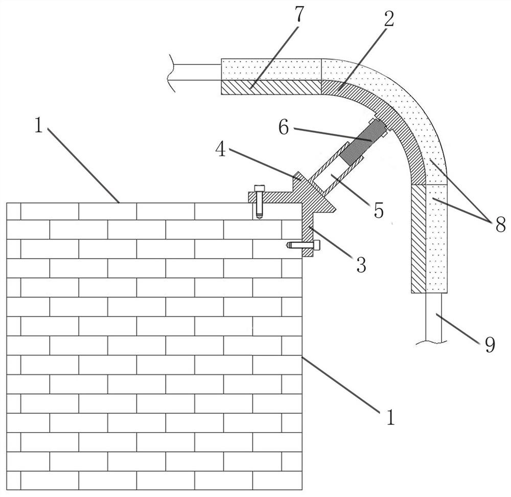
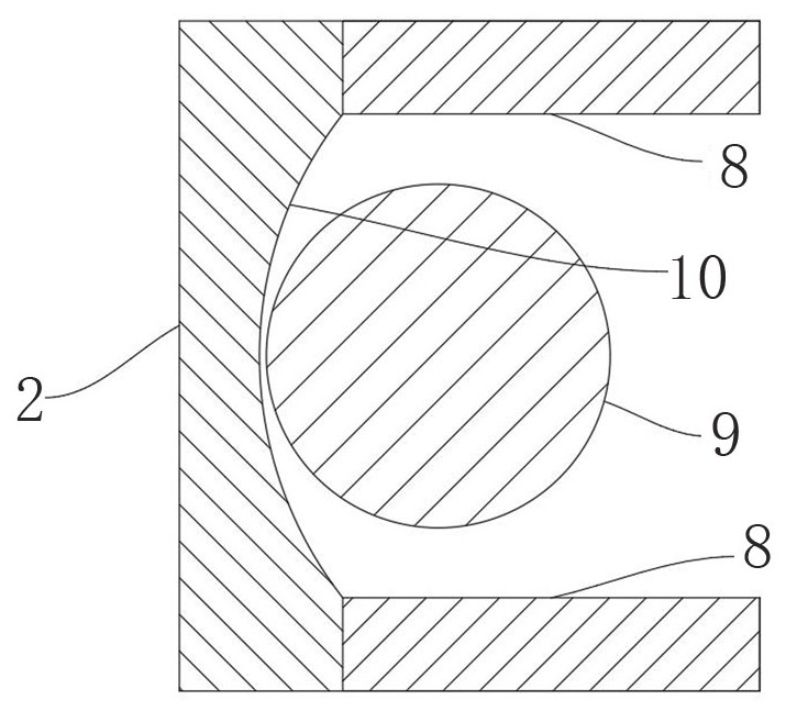
[0034] Such as figure 1 As shown, this embodiment includes a curved plate 2, a fixing part that is detachably connected to the corner of the wall 1, and is arranged between the fixing part and the curved plate 2 for adjusting the curved plate 2 and the wall 1 An adjustment component for the spacing between corners. The angle of the corner of the wall body 1 is 90°, and the fixing part includes two connecting plates 3 detachably connected with the corresponding wall body 1 and a fixing plate 4 fixedly connected with one end of the adjustment assembly, the connecting plate 3 and the fixing plate 4 are integrally formed, Among them, the two connecting plates 3 are installed on the corresponding wall 1 through mounting bolts, the angle between the fixed plate 4 and the wall 1 is 45°, and the other end of the adjustment assembly is connected to the arc plate 2 in rotation, and...

Embodiment 2

[0040] Embodiment 2 Cable installation and adjustment frame for electric power engineering construction

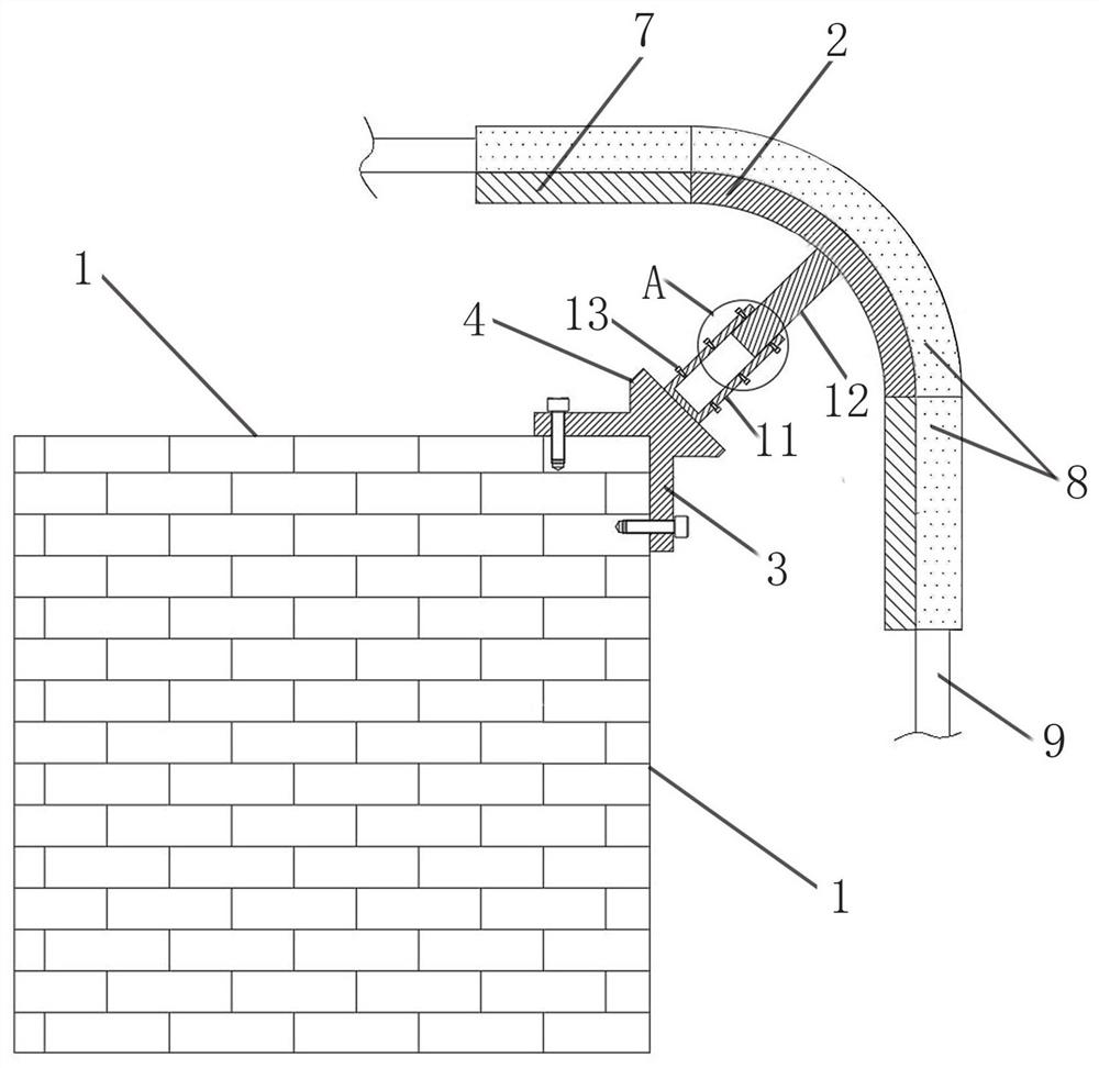
[0041] Such as image 3 and Figure 4 As shown, the structure of this embodiment is basically the same as that of Embodiment 1, the difference is that the adjustment assembly includes a sleeve 11 and a sleeve rod 12; wherein, one end of the sleeve 11 is fixedly connected to the fixed plate 4, and one end of the sleeve rod 12 is slidably connected In the casing 11, the other end of the casing rod 12 is rotatably connected to the arc-shaped plate 2, and the side wall of the casing 11 is threaded with a locking bolt 13 for fixing the casing rod 12 in the casing 11. The side wall of 11 is provided with a screw hole matched with the locking bolt 13, and the angle between the casing 11 and the wall 1 is 135°.

[0042] When this embodiment is in use, by pushing and pulling the sleeve rod 12 to make the sleeve rod 12 slide in the sleeve 11, the distance between the arc-shaped pl...


PUM


Abstract

The invention belongs to the technical field of cable installation adjusting frames, and discloses a cable installation adjusting frame for electric power engineering construction. The adjusting frame comprises an arc-shaped plate, a fixing part detachably connected to the corner of a wall body, and an adjusting assembly arranged between the fixing part and the arc-shaped plate and used for adjusting the distance between the arc-shaped plate and the corner of the wall body. One end of the adjusting assembly is fixedly connected to the fixing part, and the other end is rotatably connected to the arc-shaped plate; and the concave part of the arc-shaped plate faces the corner of the wall body. The turning radius can be adjusted by adjusting the distance between the arc-shaped plate and the corner of the wall body according to the thickness of a cable, and the adjusting frame has the advantages of being simple in structure, easy to implement and low in production cost.

Description

technical field [0001] The invention belongs to the technical field of cable installation and adjustment frames, and relates to a cable installation and adjustment frame, in particular to a cable installation and adjustment frame for electric power engineering construction. Background technique [0002] Wire and cable are a class of wire products used to transmit electrical energy and information, and play an essential role in various industries. Most of the cables in the building will be laid from the top side of the corridor by erecting the installation frame for cable laying, and when the cable laying needs to pass through the right-angled corner of the wall, it will pass the corner by bending the cable. Due to the different thickness of the cables, when the thinner cables are bent, the bending radius can be bent through the corner of the wall without damaging the cables; Large bending radii prevent damage to the cable during bending. At present, the existing installati...

Claims


Application Information

Patent Timeline
IPC IPC(8): H02G3/30
CPCH02G3/30
Inventor 陈志远米振宝李卓张勇峰赵敬
Owner 中国电建集团河北工程有限公司
Learn More