Impingement/convection/microwave oven and method

a microwave oven and convection technology, applied in the field of microwave oven and convection oven and method, can solve the problems of increasing the side-to-side footprint of the oven, increasing the preheat time, and affecting the preheating effect of the oven

Inactive Publication Date: 2007-12-06
ENODIS
View PDF99 Cites 34 Cited by
  • Summary
  • Abstract
  • Description
  • Claims
  • Application Information

AI Technical Summary

Benefits of technology

[0030] In another embodiment of the oven of the present invention, a first air filter holder and a second air filter holder that enables easy installation and removal of the first air filter and the second air filter, respectively, are provided.
[0065] In another embodiment of the method of the present invention, a first air filter holder and a second air filter holder that enables easy installation and removal of the first air filter and the second air filter, respectively, are provided.
[0076] In another embodiment of the system of the present invention, the microwave generator includes a microwave source that provides the microwave energy into the oven via a feed aperture in the vertical wall, and wherein the food rack is located below the feed aperture so as to minimize microwave energy incident to the feed aperture that is reflected by the metal pan, thereby prolonging the longevity of the microwave source.
[0080] In another embodiment of the system of the present invention, a controller and a cooling fan that cools the microwave generator are provided. The controller regulates a speed of the cooling fan based on a temperature sensed by a probe in a vicinity of the microwave facility to reduce the speed as the sensed temperature falls and to increase the speed as the sensed temperature rises.
[0100] In another embodiment of the controller of the present invention, the instructions cause the processor to perform a further step of adjusting a speed of a cooling fan of the oven to a higher speed to assist in the cool down mode.

Problems solved by technology

The countertop oven also uses a fan disposed adjacent a side wall of the oven chamber, which increases the side-to-side footprint of the oven.
However, such an oven is quite heavy and cumbersome for many applications.
Moreover, the preheat time is considerable (up to two or more hours) and cooling of the oven's exterior surfaces can be difficult and energy inefficient.
This will brown or crisp the top of a food product but not the sides or bottom because the browning effect of the impingement jets is lost when the impingement jets merge to form a blanket or are reflected from oven chamber surfaces.
This results in uneven microwave cooking as the bottom of the food product is exposed to direct microwave energy and the top of the food is exposed to indirect microwave energy.
Moreover, if metal pans are used, bottom feed microwave energy results in a large amount of reflected microwave energy to the bottom feed aperture, which can considerably reduce the useful life of the magnetrons.

Method used


Image

  • Impingement/convection/microwave oven and method
  • Impingement/convection/microwave oven and method
  • Impingement/convection/microwave oven and method

Examples


Embodiment Construction

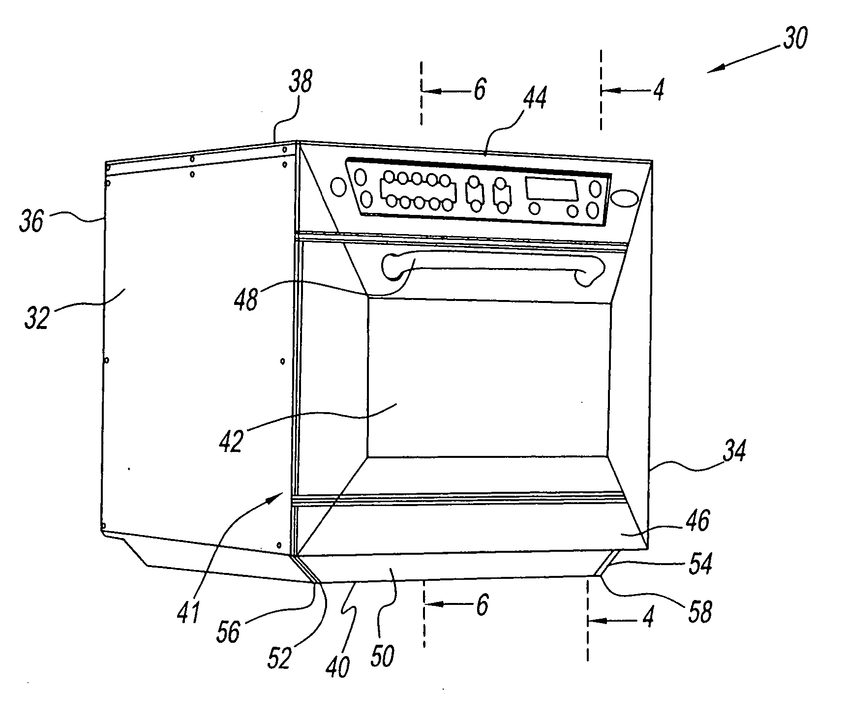
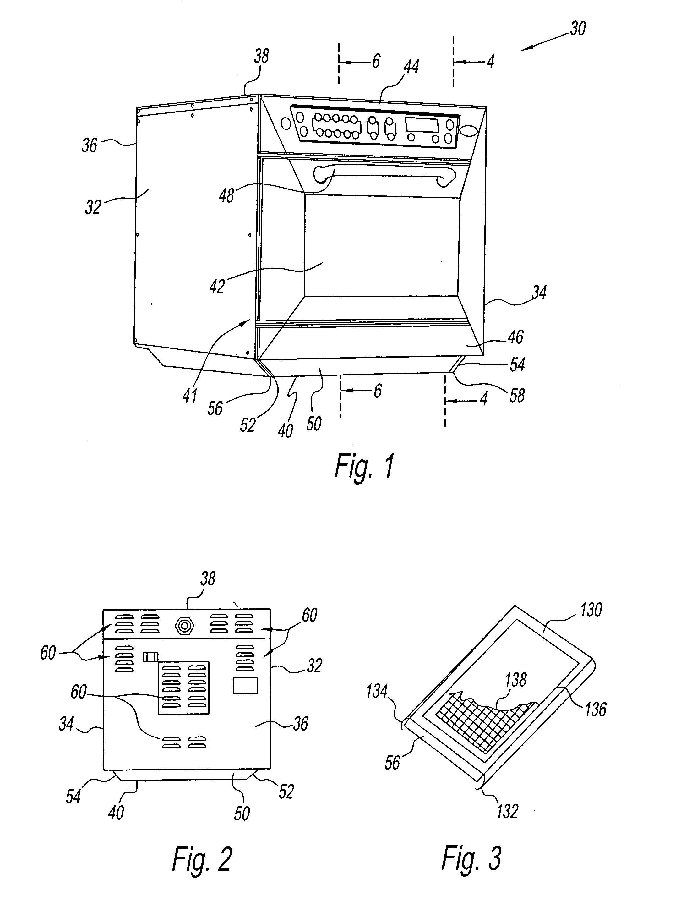
[0184] Referring to FIGS. 1 and 2, a combination oven 30 of the present invention comprises a pair of outer side walls 32 and 34, an outer back wall 36, an outer top wall 38, an outer bottom wall 40 and a front wall 41, all of which comprise an outer enclosure. Front wall 41 comprises a door 42, a control panel 44 above door 42 and a grease drawer 46 below door 42. A handle 48 is disposed on door 42 for opening the door in a pull down manner.

[0185] Outer bottom wall 40 is offset from outer side walls 32 and 34, outer back wall 36 and front wall 41. The offset is preferably a bevel 50, but could be have other shapes. An air intake port 52 and an air intake port 54 are located in opposed sides of bevel 50 adjacent outer side walls 32 and 34, respectively. Air filters 56 and 58 are disposed at air intake ports 52 and 54, respectively. Ambient air is taken in via air intake ports 52 and 54 to cool various control parts, a fan motor (not shown), outer side walls 32 and 34, outer bottom ...


PUM


Abstract

A combination oven that is operable with convection air, impingement air and microwave energy in various combinations thereof. The oven has an oven chamber and a fan box that are located front to back. A fan in the fan box circulates heated air by discharging via openings in a top and a bottom and taking in via an intermediate opening of a baffle plate. Impingement plates are easily installed and removed in the oven chamber to provide impingement air upwardly or downwardly. At least one of the impingement plates is installed and removed by a sliding motion. Microwave energy is provided through the side walls of the oven chamber. Intake ports for cooling air are located in a bevel between the side walls and bottom wall of the oven's outer enclosure so as to allow the oven to be located right next to other structures, such as a wall. An interlock assembly is also provided for the oven door.

Description

CROSS-REFERENCED APPLICATIONS [0001] This application is a divisional application of U.S. patent application, Ser. No. 11 / 302,638, filed on Dec. 14, 2005, which claims the benefit of U.S. Provisional Patent Application, Ser. No. 60 / 635,857, filed on Dec. 14, 2004, U.S. Provisional Patent Application, Ser. No. 60 / 682,594, filed on May 19, 2005, and U.S. Provisional Patent Application, Ser. No. 60 / 735,241, filed on Nov. 9, 2005, the entire contents of each are hereby incorporated by reference.FIELD OF THE INVENTION [0002] This invention relates to new and improved cooking ovens, systems, oven controllers and methods concerning microwave, convection and impingement cooking separately and in various combinations as well as cooling and interlock features for cooking ovens in general. BACKGROUND OF THE INVENTION [0003] A cooking oven that has both convection and impingement modes is shown in U.S. Pat. No. 5,345,923 as a countertop oven with one or more removable air impingement supply str...

Claims


Application Information

Patent Timeline
Patent Type & Authority Applications(United States)
IPC IPC(8): H05B6/64
CPCA21B1/245H05B6/6476H05B6/6426H05B6/642H05B6/64
Inventor CLAESSON, JANSTANGER, KEITH A.THORNEYWORK, NIGELBROWN, ANDREWCRAYFOURD, DAVICHARTER, DAVIDDAY, WILLIAM
Owner ENODIS
Why Eureka
Try Eureka