Rotatable and removable auxiliary eyewear system with snap alignment

Inactive Publication Date: 2005-04-28
ASPEX EYEWEAR +1
View PDF1 Cites 31 Cited by
  • Summary
  • Abstract
  • Description
  • Claims
  • Application Information

AI Technical Summary

Benefits of technology

[0015] A primary advantage of the present invention is that it provides accurate, snap alignment of the auxiliary lens assembly to the primary lens assembly when raised and when lowered back into position. Another advantage of the present invention is that it provides an auxiliary lens assembly and primary lens assembly combination in which the auxiliary lens assembly is easily installed and removed from the primary lens assembly. Another advantage of the present invention is that it provides a means of temporary displacement of the auxiliary lenses without a need for complete removal and separate storage of the auxiliary lens assembly.
[0016] Another advantage of the present invention is that it provides an auxiliary lens assembly and primary lens assembly combination which resists unintended disengagement. Another advantage of the present invention is that it is simple and aesthetically attractive. Another advantage of the present invention is that it provides the fully perpendicular alignment of the auxiliary assembly to the primary assembly without contacting the forehead of the person wearing the device. Another advantage of the present invention is that it provides a primary lens assembly optionally compatible with non-rotatable auxiliary lens assemblies. Another advantage of the present invention is that it provides optional embodiments that can be constructed without magnets.
[0017] Other advantages of the present invention will become apparent from the following descriptions, taken in connection with the accompanying drawings, wherein, by way of illustration and example, an embodiment of the present invention is disclosed. As referred to hereinabove, the “present invention” refers to one or more embo

Problems solved by technology

A significant disadvantage of this design is that it is unattractive, overly complicated, impossible to segregate from the primary frame, and does not permit or accommodate anyone other than far sighted individuals.
A significant disadvantage of this design is that it is unattractive, overly complicated, and resist easy and immediate removal of the auxiliary lens assembly.
As stated, these and other mechanically “clipped-on” devices for holding auxiliary lenses are cumbersome and unattractive.
They do not enjoy the advantages of the early flip-up designs, which permitted quick movement of the auxiliary assembly out of alignment with the primary assembly without separating them from the primary assembly.
A significant disadvantage of this design is that it is unstable, relying on tenuous repositioning, and magnetic

Method used


Image

  • Rotatable and removable auxiliary eyewear system with snap alignment
  • Rotatable and removable auxiliary eyewear system with snap alignment
  • Rotatable and removable auxiliary eyewear system with snap alignment

Examples


Example

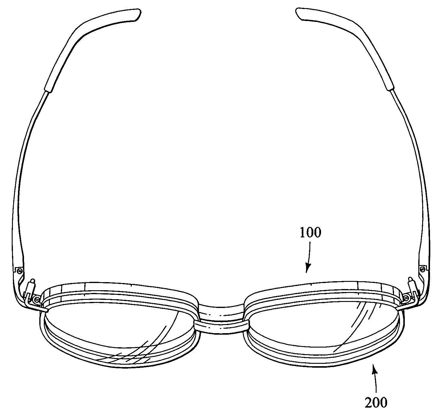
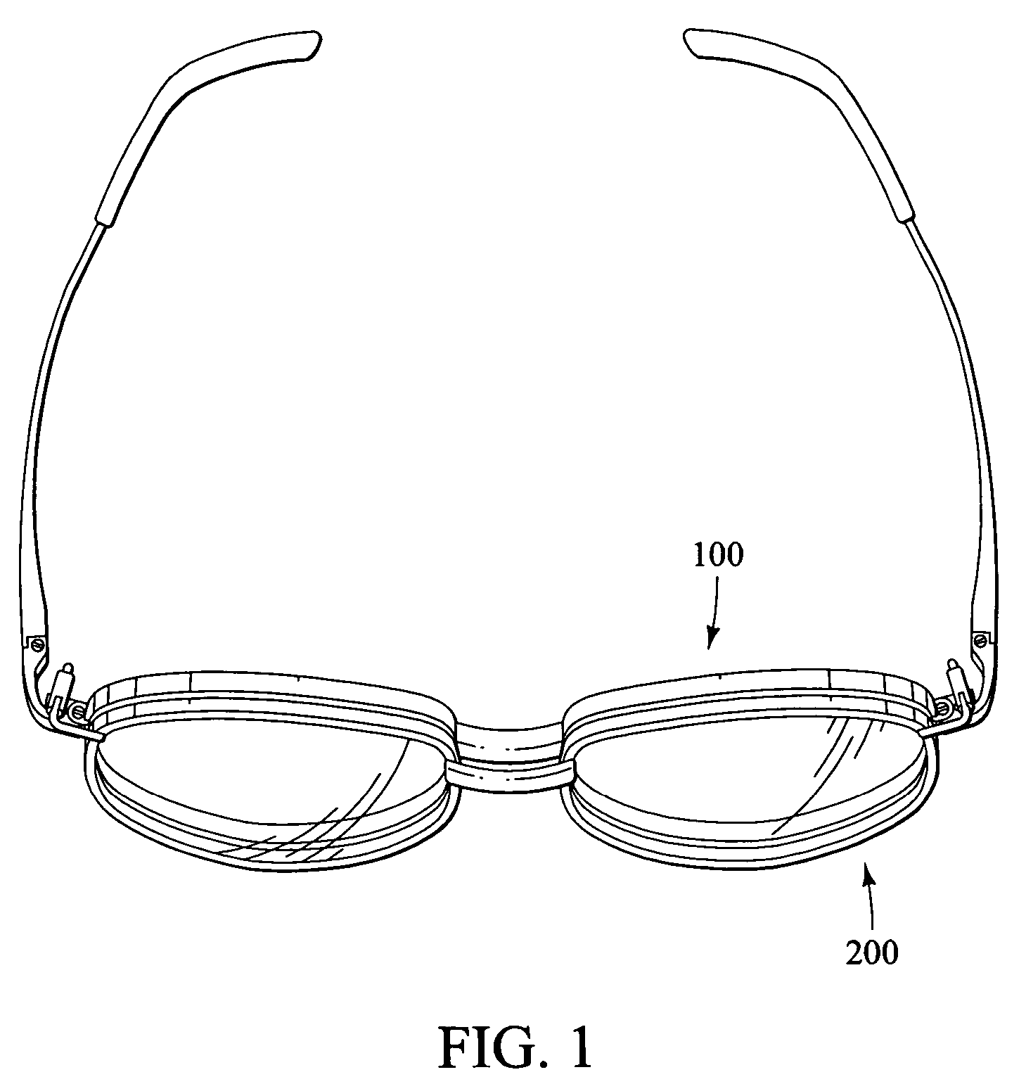
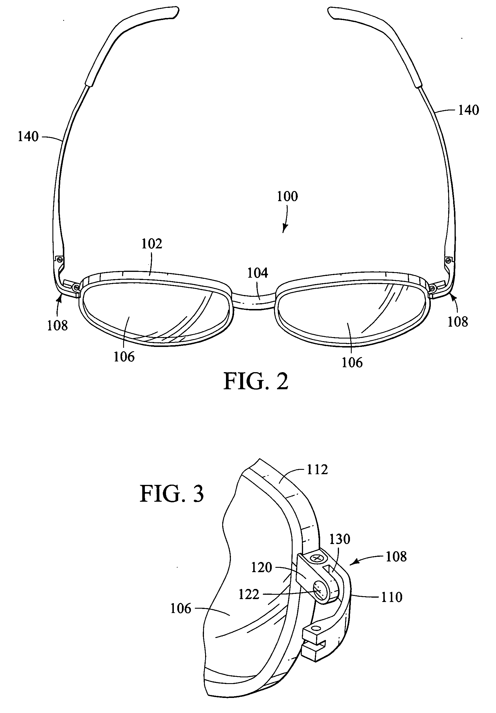
[0064]FIG. 13 discloses a second embodiment. In this embodiment, retainers 232 are solid (have no magnets), and are made of magnetic material. Retainers 232 may be formed integrally from the ends of brackets 210. Retainers 232 are subject to magnetic attraction from primary magnets 122.

Example

[0065]FIG. 14 discloses a third embodiment. In this embodiment, rear extension portions 120 are solid, (have no magnets) and are made of magnetic material. Rear extension portions 120 are subject to magnetic attraction from auxiliary magnets 232.

Example

[0066]FIG. 15 discloses a fourth embodiment of auxiliary lens assembly 200. In this somewhat simpler embodiment, auxiliary extensions 208 do not incorporate keyseat 214, rocker 220 or arm 230. Retainers 232 are attached to the ends of brackets 210. Auxiliary magnets 234 are contained in retainers 232. This configuration of auxiliary lens assembly 200 represents a known and readily available configuration. FIG. 16 discloses the complimentary primary lens assembly 100, which is the same as that of FIG. 3. FIG. 17 illustrates the auxiliary lens assembly 200 partially combined with primary lens assembly 100. FIG. 18 illustrates the full engagement of auxiliary lens assembly 200 with primary lens assembly 100. This combination demonstrates the compatibility of the primary lens assembly 100 of the present invention with existing, non-rotatable auxiliary lens assemblies 200.


PUM


Abstract

The present invention discloses a unique and novel system for attaching an auxiliary lens assembly to a primary lens assembly in which the attachment includes two alternative positions, a lowered position and a raised position. In the lower position, the person wearing the eyewear system views through both the primary lenses and auxiliary lenses. In the raised position, the person wearing the eyewear system views only through the primary lenses. As a further option, the auxiliary lens assembly is easily removable from the primary lens assembly, allowing for separate storage of the auxiliary lens assembly when not needed. Slotted extensions on the primary lens frame receive retainers attached to auxiliary extensions on the auxiliary lens assembly. Each auxiliary extension has a rocker pivotally attached to a keyseat. An internal spring urges the rocker into snap alignment with the surfaces of the keyseat.

Description

RELATED ART [0001] This patent claims priority to U.S. Provisional Application 60 / 514,323, filed Oct. 24, 2003.TECHNICAL FIELD OF INVENTION [0002] The present invention relates to eyewear, and in particular, to a design for and auxiliary lens assembly and primary lens assembly combination in which the auxiliary lens assembly is adapted for rotatable and removable attachment to the primary lens assembly. More specifically, the present invention discloses to an auxiliary eyewear support system that utilizes pivotal hinges integral to the auxiliary frame, which permit rotation of the auxiliary frame from a first position in which the auxiliary lenses are substantially parallel to the primary lenses, to a second position in which the auxiliary frame is rotated into a position substantially perpendicular to the orientation of the primary frame. BACKGROUND OF THE INVENTION [0003] It has long been desirable to have a removable auxiliary lenses attached to eyeglasses. Professional baseball ...

Claims


Application Information

Patent Timeline
IPC IPC(8): G02C9/00
CPCG02C2200/02G02C9/00
Inventor SMITH, GREGLANGLEY, PHILIP
Owner ASPEX EYEWEAR
Why Eureka
Try Eureka