Image forming apparatus and image forming method

Inactive Publication Date: 2008-05-29
KONICA MINOLTA BUSINESS TECH INC
View PDF6 Cites 1 Cited by
  • Summary
  • Abstract
  • Description
  • Claims
  • Application Information

AI Technical Summary

Benefits of technology

[0014]Accordingly, an objective of the present invention is to solve the aforesaid problems and to provide an image forming apparatus and an image forming method wherein a fo

Problems solved by technology

Therefore, when an edge portion of a transfer sheet after fixing is curled or is fluttered, its influence causes a form of an edge or a position of passage at the sensor to be unstable, and there is a fear that a detection error grows greater between the image detection sensor and the first surface reading sensor.
Accordingly, it is difficult to align accurately a position of the image formed on the front surface of the sheet and a position of the image formed on the rear surface of the transfer sheet.
Accordingly, there is a fear that a detection erro

Method used


Image

  • Image forming apparatus and image forming method
  • Image forming apparatus and image forming method
  • Image forming apparatus and image forming method

Examples


Example

EXAMPLE 1

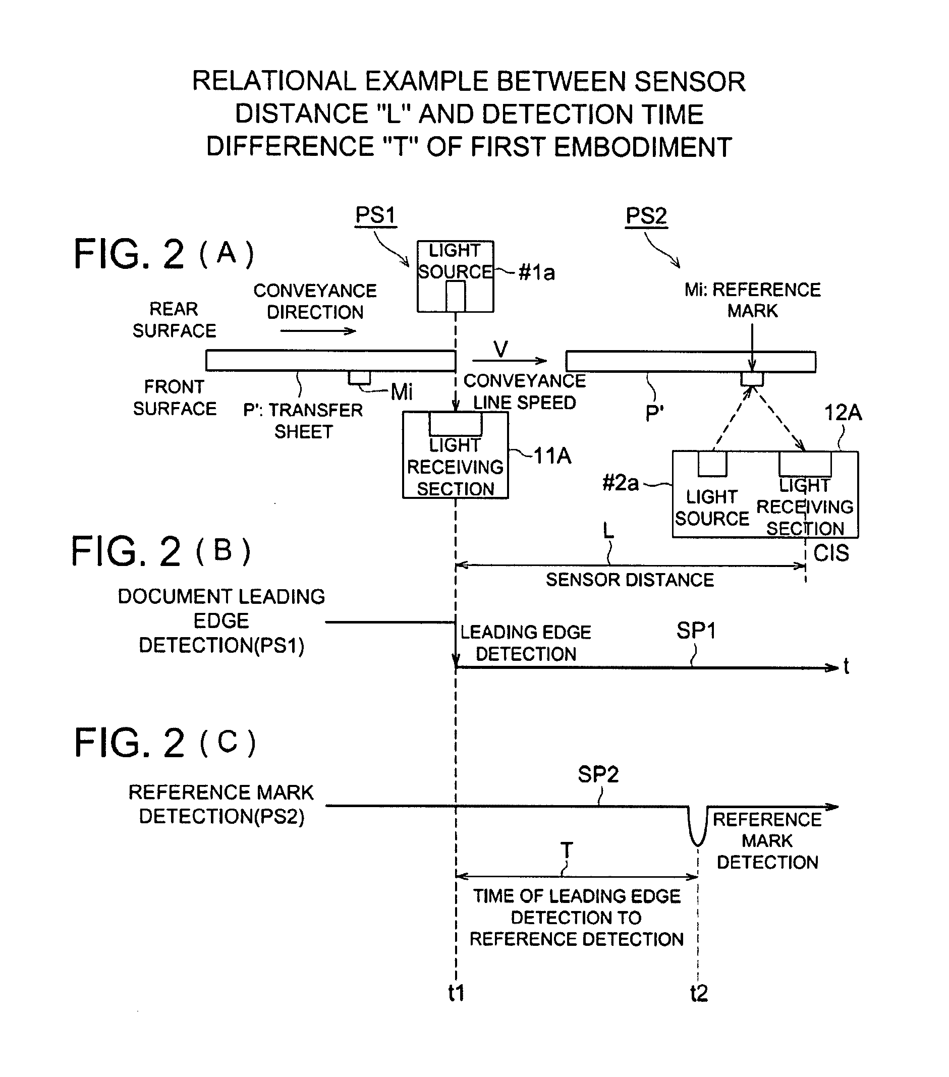
[0055]Each of FIGS. 2(A)-2(C) is a diagram showing an example of relationship between a distance from sensor to sensor L and a detection time difference T, as the First Example.

[0056]The distance from sensor to sensor L shown in FIG. 2(A) is a distance between an optical axis of light receiving section 11A of the leading edge detection sensor PS1 and an optical axis of light receiving section 12A of mark detection sensor PS2. In this example, if a focal length for image-capturing of reference mark Mi can be secured, a position of arranging the mark detection sensor PS2 is not restricted. However, it is preferable if the distance from sensor to sensor L is shorter, because an influence of fluctuations in transfer sheet conveyance speed is less if the mark detection sensor PS2 is arranged to be as close as possible to the leading edge detection sensor PS1 provided adjacently. The distance from sensor to sensor L is established, for example, to be about 50 mm (30-70 mm).

[0057]...

Example

EXAMPLE 2

[0095]FIG. 8 is a perspective view showing an example of structure of optical-sensor PS3 of a multi-functional type relating to the Second Example.

[0096]In this example, detection of the leading edge of transfer sheet P′ and detection of a position of a reference mark are conducted respectively by optical-sensor PS3 having different sensing systems with the same light receiving section 13A, whereby, a distance from the leading edge of a transfer sheet to an image of a reference mark is detected.

[0097]The optical-sensor PS3 of a multi-functional type shown in FIG. 8 is one capable of being installed in color printer 100, and it has a sheet leading edge detection function of leading edge detection sensor PS1 and a reference mark detection function of mark detection sensor PS2. The optical-sensor PS3 is provided on each of both right and left sides of the sheet conveyance path for detecting right and left on the leading edge and right and left marks, in the direction perpendic...


PUM


Abstract

An image forming apparatus provided with an image forming section forming a reference mark at the position being away from the leading edge of the front surface of a sheet by a prescribed length, and forming an image for the front surface based on the forming position of the reference mark, a transfer sheet reversing section reversing the sheet, a leading edge detection sensor detecting the leading edge of the rear surface of the sheet and a mark detection sensor detecting the forming position of the reference mark on the sheet based on the leading edge of the rear surface of the transfer sheet, and the image forming section forms an image on the rear surface of the transfer sheet based on the forming position of the reference mark on the sheet whose reference point is the leading edge of the rear surface of the transfer sheet.

Description

BACKGROUND OF THE INVENTION[0001]The present invention relates to an image forming apparatus and an image forming method which can be appropriately applied to a color printer, a color copying machine equipped with a two-sided image-forming mode that forms color images on the front and rear surfaces of a sheet and to a multifunctional machine having functions of the foregoing.[0002]In recent years, use of a color printer and a color copying machine both being of a tandem type and of a color multifunctional machine including functions of the aforesaid items has become popular. In the image forming apparatus equipped with the single-sided image-forming mode of this kind, when reproducing R color, G color and B color of a color image, toner images for respective colors of yellow (Y), magenta (M), cyan (C) and black (BK) are formed on photoconductor drums for respective colors, and the toner images for respective colors formed on the photoconductor drums for respective colors are superpo...

Claims


Application Information

Patent Timeline
IPC IPC(8): G06K1/00
CPCG03G15/5062G03G15/238
Inventor OYAMA, HIROSHISOMA, UTAMITAKAHASHI, ATSUSHIMATSUDAIRA, TADASHIPENG, YOUBAOKAWASAKI, SHINPEI
Owner KONICA MINOLTA BUSINESS TECH INC
Why Eureka
Try Eureka