Alignment method, alignment apparatus, and exposure apparatus

Active Publication Date: 2012-07-05
V TECH CO LTD
View PDF0 Cites 2 Cited by
  • Summary
  • Abstract
  • Description
  • Claims
  • Application Information

AI Technical Summary

Benefits of technology

[0024]Still further, according to the invention of a third, eighth or eleventh aspect, the positions of the patterns can be identified more accurately. This enables the accuracy of the alignment between the object to be exposed and the photomask to be further enhanced.
[0025]Moreover, according to the invention of a fourth aspect, the positions of the patterns of the object to be exposed made of an opaque substrate can be easily detected.
[0026]Furthermore, according to the invention of a fifth aspect, the openings of the photomask can be accurately aligned even with a TFT substrate having a wiring pattern within a pixel.
[0027]According to the invention of a ninth aspect, even in the case in which the patterns formed on the object to be exposed each have a complex shape, it is possible to easily detect the positions of

Problems solved by technology

However, for a pattern having a complex shape such as a wiring pattern within a pixel such as, for example, a TFT substrate or a pattern having a complex outline shape obtained by epi-illumination, it is difficult to detect a reference po

Method used


Image

  • Alignment method, alignment apparatus, and exposure apparatus
  • Alignment method, alignment apparatus, and exposure apparatus
  • Alignment method, alignment apparatus, and exposure apparatus

Examples


Example

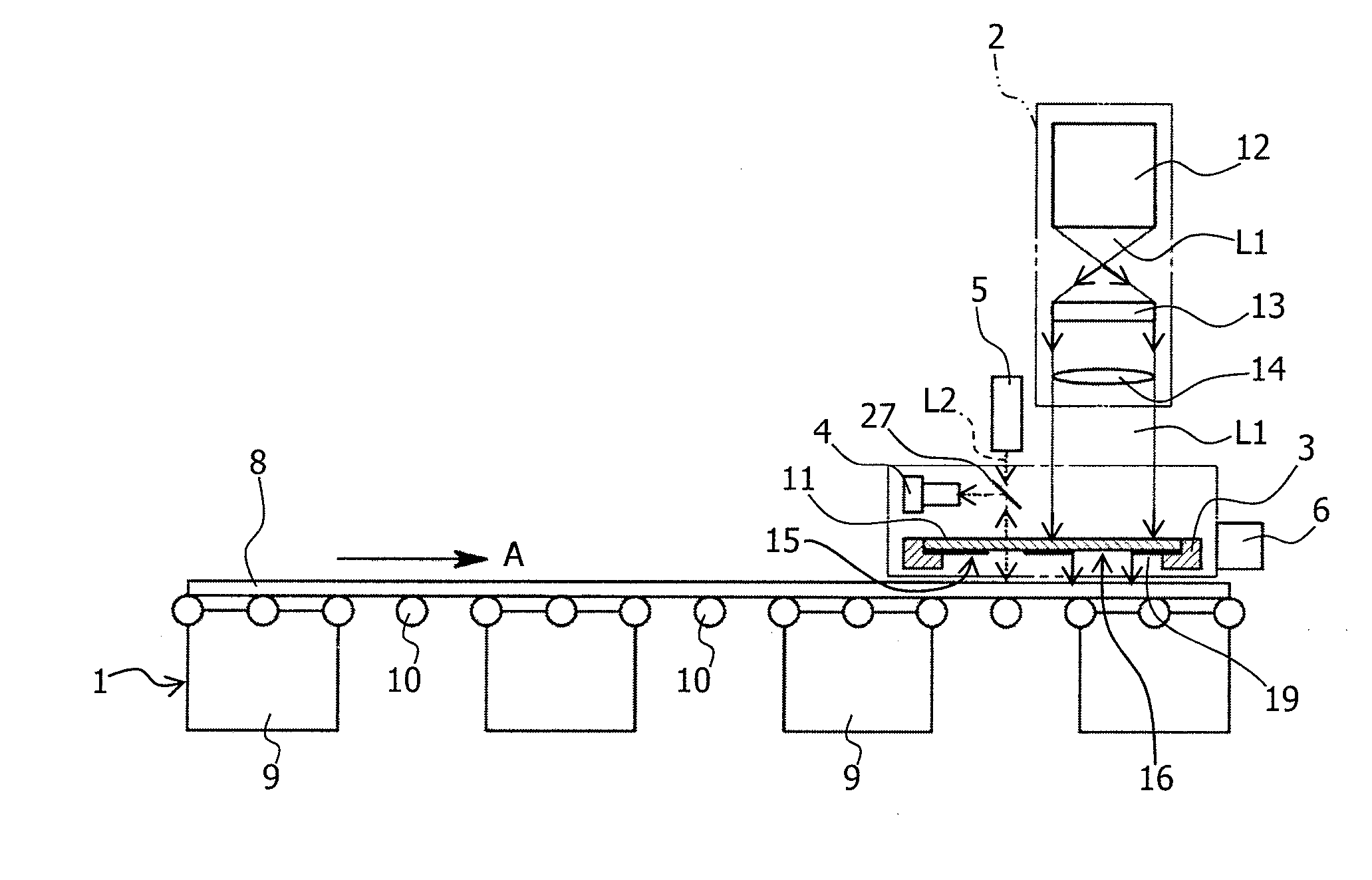
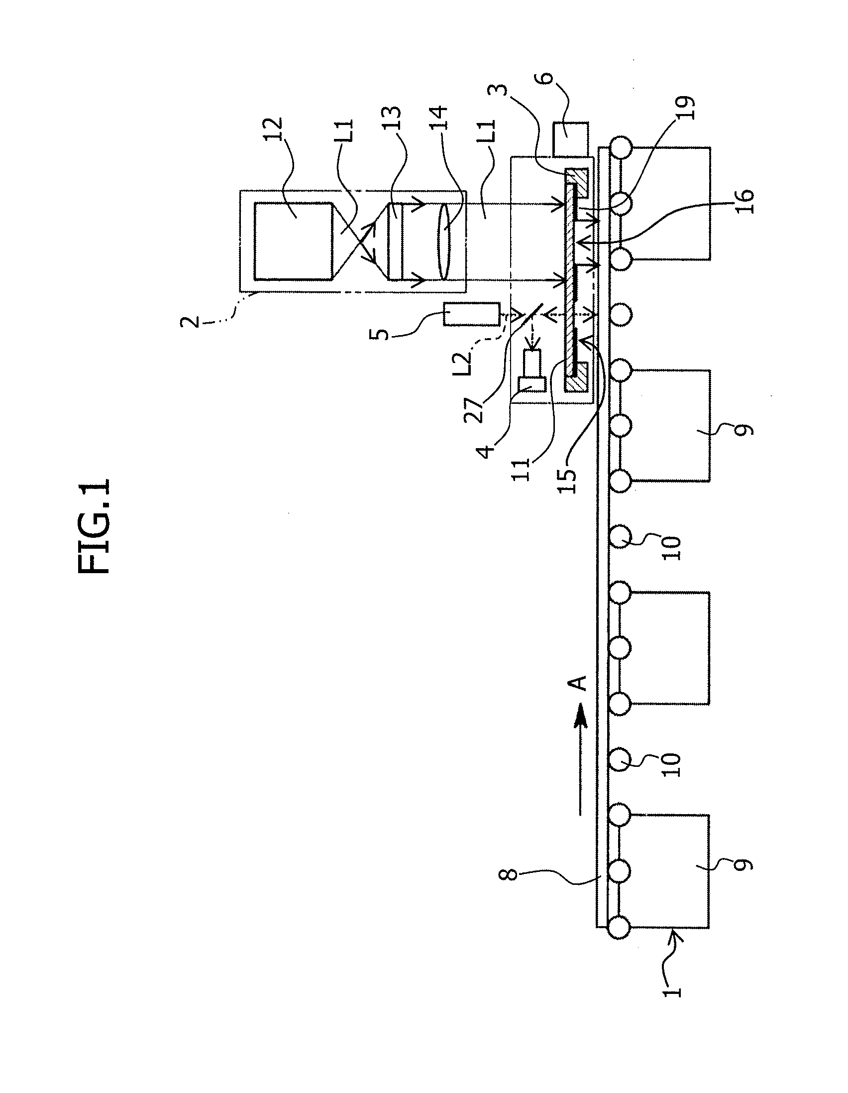
[0035]Hereinafter, preferred embodiments of the present invention will be described in detail on the basis of appended drawings. FIG. 1 is a front view illustrating an embodiment of an exposure apparatus according to the present invention. The exposure apparatus exposes an object to be exposed with uniform patterns arranged in a matrix and being conveyed in a direction with a photomask aligned with the object to be exposed. The exposure apparatus includes a conveying device 1, an exposure optical system 2, a mask stage 3, an imaging device 4, an illumination light source 5, and an alignment apparatus 6.

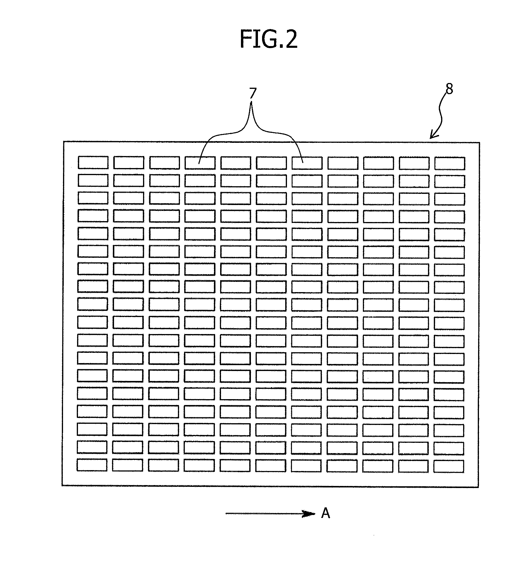
[0036]This specification describes a case in which, as illustrated in FIG. 2, for example, the object to be exposed is a color filter substrate 8, in which rectangular pixels 7 (patterns) on a black matrix are formed in a matrix, and is conveyed in the arrow A direction as illustrated in FIG. 2.

[0037]The above conveying device 1 conveys the color filter substrate 8 placed on the top t...


PUM


Abstract

In the present invention, the number of brightness changes detected at the same position while a substrate moves by a certain distance is added up, a plurality of edge count data arranged corresponding to the detected positions of the brightness changes is obtained, a plurality of correlation value data by performing a correlation operation for the plurality of calculated edge count data while moving a template is obtained, positions of the plurality of patterns based on a plurality of correlation value data exceeding a predetermined threshold value are identified, a position of a pattern close to a target position of an imaging device is selected, and a photomask is moved in the direction substantially orthogonal to the conveying direction of the substrate so that the amount of the position displacement between the selected position of the pattern and the target position of the imaging device is a predetermined value.

Description

[0001]This application is a continuation of PCT / JP2010 / 060088, filed on Jun. 15, 2010.BACKGROUND OF THE INVENTION[0002]1. Field of the Invention[0003]The present invention relates to an alignment method for aligning a photomask with an object to be exposed with uniform patterns arranged in a matrix and conveyed in a direction, and more specifically to an alignment method, an alignment apparatus, and an exposure apparatus capable of performing highly accurate alignment for a pattern having a complex shape.[0004]2. Description of Related Art[0005]In this type of conventional alignment method, an imaging device, which has a plurality of light receiving elements arranged in a straight line in a direction orthogonal to a conveying direction of a color filter substrate, captures an image of a plurality of rectangular pixels formed on a color filter substrate (an object to be exposed), detect the position of a left-side edge portion of a left-end pixel on the color filter substrate on the ...

Claims


Application Information

Patent Timeline
IPC IPC(8): G03B27/42G03B27/32
CPCG03F9/00G03F7/70775G03F7/70791G03F9/7003
Inventor IWAMOTO, TAKAMITSU
Owner V TECH CO LTD
Why Eureka
Try Eureka