Power transmission device, power transmission and receiving device, method for detecting power receiving device, power receiving device detection program, and semiconductor device

Inactive Publication Date: 2016-08-04
DEXERIALS CORP
View PDF3 Cites 10 Cited by
  • Summary
  • Abstract
  • Description
  • Claims
  • Application Information

AI Technical Summary

Benefits of technology

[0021]According to the present invention, since the resonance circuit is driven at the three or more drive frequencies, a difference between a drive current waveform obtained when a power receiving device is disposed and a drive current waveform obtained when a foreign object such as a metal is disposed is clear, and the power receiving device can be easily detected within a short period of time.
[0022]FIG. 1 is a block diagram showing a configuration of a power transmission device according to an embodiment to which the present invention is applied.
[0023]FIG. 2A is a block diagram showing a configuration of a main part of a power transmission system including the power receiving device according to an embodiment to which the present invention is applied. FIG. 2B is a block diagram showing a configuration of a resonance circuit in a detail of FIG. 2A.
[0024]FIGS. 3A and 3B are circuit diagrams showing a configuration to change resonance frequencies of the resonance circuit. FIG.

Problems solved by technology

When polling is regularly performed, in a mobile phone, a smart phone

Method used


Image

  • Power transmission device, power transmission and receiving device, method for detecting power receiving device, power receiving device detection program, and semiconductor device
  • Power transmission device, power transmission and receiving device, method for detecting power receiving device, power receiving device detection program, and semiconductor device
  • Power transmission device, power transmission and receiving device, method for detecting power receiving device, power receiving device detection program, and semiconductor device

Examples


Example

[0038]Modes for executing the present invention will be described below in detail with reference to the accompanying drawings. The present invention is not limited to only the following embodiments, and can be variously changed without departing from the spirit and scope of the present invention as a matter of course. The explanation will be made in the following order.

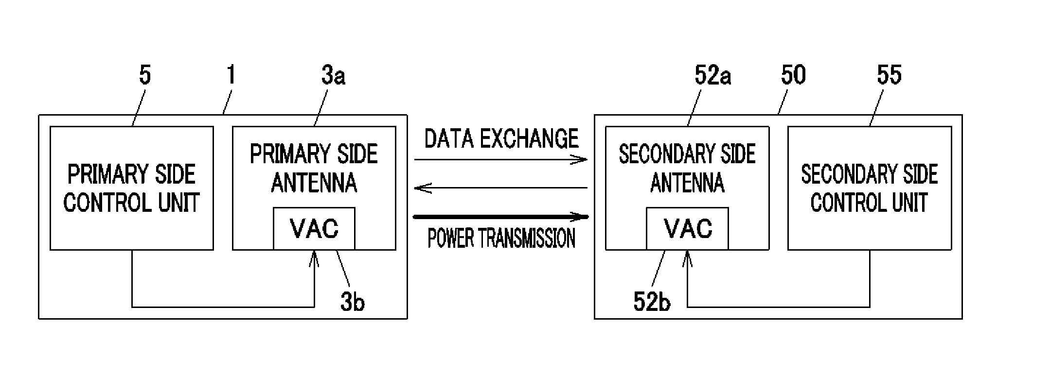
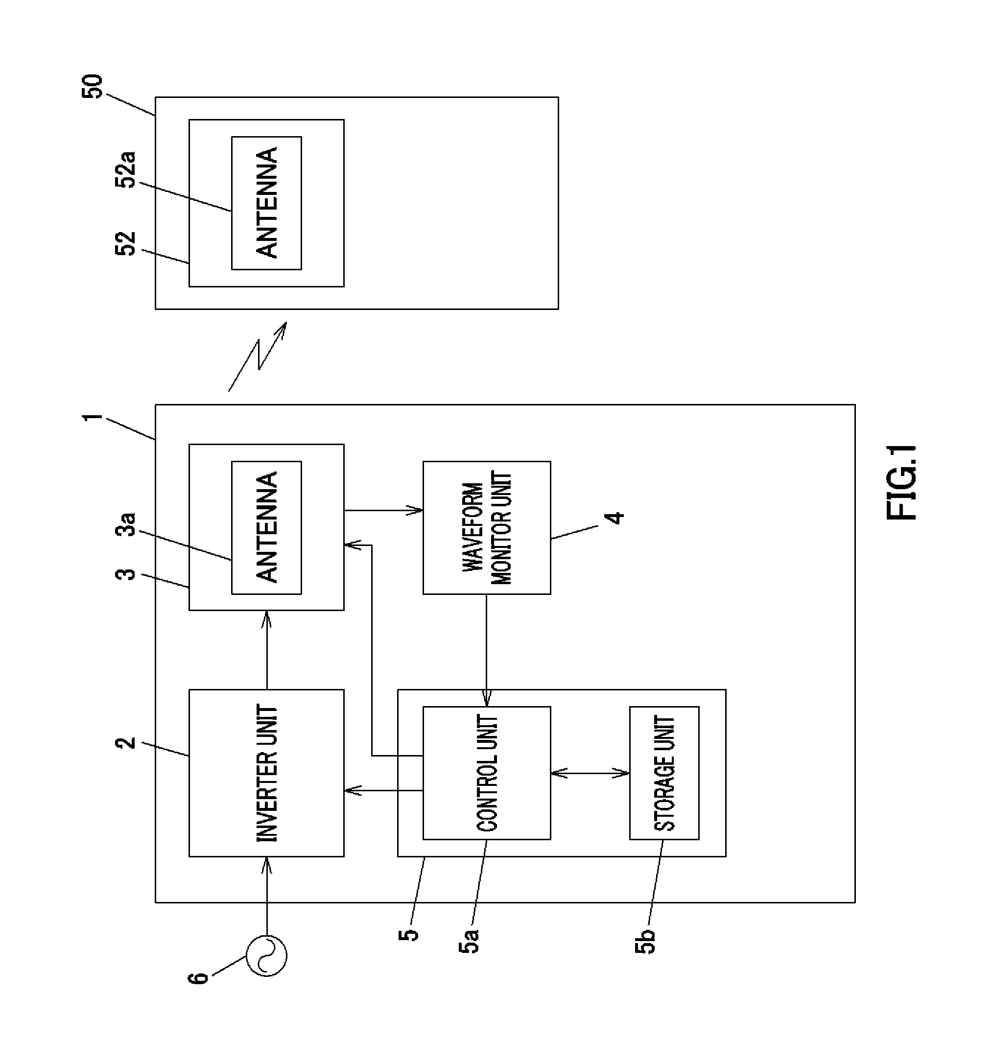
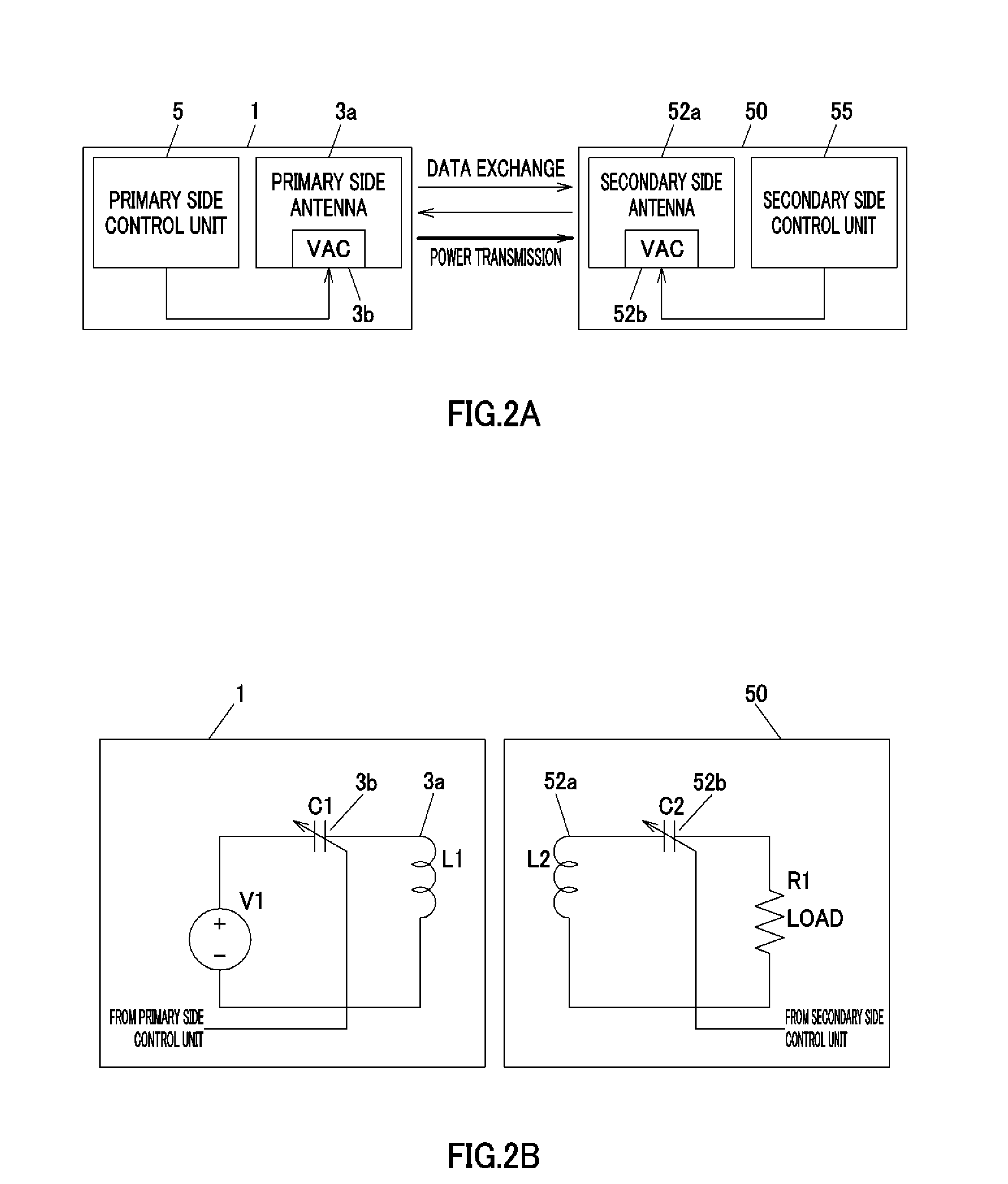
[0039]1. Configuration of power transmission device

[0040]2. Principle and operation of power transmission device

[0041]2-1. Difference between frequency characteristics of antenna currents in the presence of power receiving device and in the presence of foreign object

[0042]2-2. Detection of difference between frequency characteristics of antenna currents in weak coupling

[0043]2-3. Resonance frequency deviation on power receiving device side

[0044]2-4. Detection of difference between frequency characteristics of antenna currents when a coupling coefficient changes

[0045]2-5. Setting of detection pattern

[0046]3. Method for...


PUM


Abstract

To provide a power transmission device that can accurately discriminate a device or apparatus placed on a secondary side from a foreign object placed on the secondary side without adding a complex circuit. The power transmission device includes a control unit that sets a drive frequency of a signal for driving a resonance circuit, an inverter unit that drives the resonance circuit at three or more drive frequencies on the basis of a setting of the control unit, and a waveform monitor unit that detects a drive waveform of the resonance circuit. The control unit sets three or more drive frequencies according to a procedure of a program stored in a storage unit, compares signal data at the drive frequencies detected by a drive waveform detecting unit with each other, and detects a power receiving device on the basis of the comparison result.

Description

BACKGROUND OF THE INVENTION[0001]1. Field of the Invention[0002]This invention relates to a power transmission device, a power transmission and receiving device, a method for detecting power receiving device, a power receiving device detection program, and a semiconductor device that transmit or receive an electric power from a noncontact communication device. The present application claims priority based on Japanese Patent Application No. 2013-60646 filed in Japan on Mar. 22, 2013. The total contents of the patent application are to be incorporated by reference into the present application.[0003]2. Description of Related Art[0004]A noncontact communication technique using electromagnetic induction has been popularly applied to IC cards such as FeliCa (registered trademark), Mifare (registered trademark), and NFC (Near Filed Communication). In recent years, the noncontact communication technique has been also applied to a noncontact power charging (discharging) technique typified by...

Claims


Application Information

Patent Timeline
IPC IPC(8): H02J50/12H02J50/80H02J50/60H02J7/00
CPCH02J50/12H02J50/60H02J50/80H02J50/90
Inventor KANNO, MASAYOSHI
Owner DEXERIALS CORP
Why Eureka
Try Eureka