Method of operating a converter circuit

Inactive Publication Date: 2007-12-27
ABB (SCHWEIZ) AG
View PDF9 Cites 12 Cited by
  • Summary
  • Abstract
  • Description
  • Claims
  • Application Information

AI Technical Summary

Benefits of technology

[0006]In an exemplary method of operating a converter circuit, the converter circuit has a converter unit with a multiplicity of controllable power semiconductor switches, wherein the converter unit is connected at the AC voltage end to an electrical AC voltage network and the controllable power semiconductor switches are controlled by means of a control signal. For example, the phase voltages of the AC voltage network are first determined, e.g., by measurement. After that, the negative sequence amplitude of the phase voltages and the Park-Clarke transformation amplitude of the phase voltages are calculated. Furthermore, the negative sequence amplitude of the phase voltages is monitored at a settable value and the Park-Clarke transformation amplitude of the phase voltages is monitored at a settable value. If the negative sequence amplitude of the phase voltages exceeds the settable value or if the Park-Clarke transformation amplitude of the phase voltages falls below the settable value, the controllable power semiconductor switches are locked by means of the control signal. By mo

Problems solved by technology

The problem with a converter circuit of this type is that where there are asymmetrical phase voltages UNa, UNb, UNc in the AC voltage network 2, i.e. different phase angles of the phase voltages UNa, UNb, UNc relative to one another and/or different amplitudes of the phase voltages UNa, UNb, UNc to one another and/or different frequencies of the phase vo

Method used


Image

  • Method of operating a converter circuit
  • Method of operating a converter circuit
  • Method of operating a converter circuit

Examples


Example

[0009]The references used in the drawing and their meanings are summarised in the reference list. As a rule, identical parts are given the same reference in the figure. The exemplary embodiments are described as examples without any limiting effect.

DETAILED DESCRIPTION

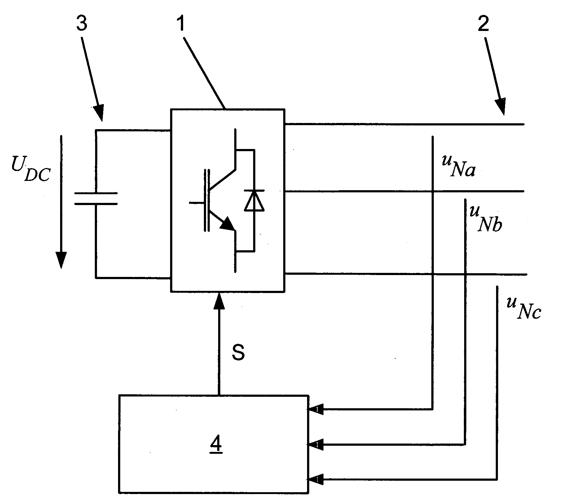
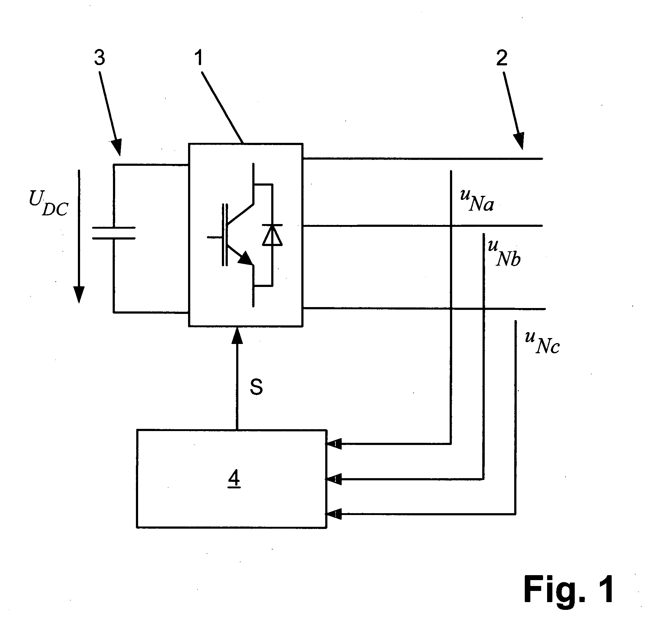
[0010]An exemplary embodiment of a converter circuit is shown in FIG. 1. The converter circuit comprises a converter unit 1 for switching at least two switching voltage levels. At the AC voltage end, the converter unit 1 is connected to an electrical AC voltage network 2. Furthermore, a capacitive energy store 3 is connected to the converter unit 1, which is typically formed by one or more capacitors. In order to operate the converter circuit, a control device 4 is provided, which controls the controllable power semiconductor switches by means of a control signal S according to the method during operation of the converter circuit, wherein the control signal S is generated by means of a look-up table, in which control s...


PUM


Abstract

A method of operating a converter circuit is disclosed, wherein the converter circuit has a converter unit with a multiplicity of controllable power semiconductor switches and the converter unit is connected at the AC voltage end to an electrical AC voltage network. According to the method, the controllable power semiconductor switches are controlled by means of a control signal. To protect the converter circuit in the event of asymmetrical phase voltages occurring in an AC voltage network connected to the converter circuit, the phase voltages (UNa, UNb, UNc) in the AC voltage network are determined, the negative sequence amplitude of the phase voltages (UNn,A) is calculated, the Park-Clarke transformation amplitude of the phase voltages (UNdq,A) is calculated, the negative sequence amplitude of the phase voltages (UNn,A) is monitored at a settable value, the Park-Clarke transformation amplitude of the phase voltages (UNdq,A) is monitored at a settable value and the controllable power semiconductor switches are locked by means of the control signal if the negative sequence amplitude of the phase voltages (UNn,A) exceeds the settable value or if the Park-Clarke transformation amplitude of the phase voltages (UNdq,A) falls short of the settable value.

Description

RELATED APPLICATIONS[0001]This application claims priority under 35 U.S.C. §119 to EP Application 06405267.3 filed in Europe on Jun. 23, 2006, the entire contents of which are hereby incorporated by reference in their entireties.TECHNICAL FIELD[0002]The disclosure relates to the field of power electronics. It is based on a method of operating a converter circuit.BACKGROUND INFORMATION[0003]Known converter circuits comprise a converter unit with a multiplicity of controllable power semiconductor switches, which are connected in a known way to the circuit of at least two switching voltage levels. A converter circuit of this type is shown in FIG. 1. At the AC voltage end, the converter unit 1 is connected to an electrical AC voltage network 2. In addition, a capacitive energy store 3 is connected to the converter unit 1, which is currently made up of one or more capacitors. In order to operate the converter circuit, a control device 4 is typically provided, which controls the controlla...

Claims


Application Information

Patent Timeline
IPC IPC(8): G05F1/00
CPCG01R29/16Y02E40/22H02M1/32H02J3/1842Y02E40/20
Inventor CONTICELLI, FABIOBEISER, DIRKBOHREN, PATRICK
Owner ABB (SCHWEIZ) AG
Why Eureka
Try Eureka