

Aberration measuring method and projection exposure apparatus
- Summary
- Abstract
- Description
- Claims
- Application Information
AI Technical Summary
Benefits of technology
Problems solved by technology
Method used
Image

Examples
Embodiment Construction
[0040]Preferred embodiments of the present invention will be described with reference to the attached drawings.
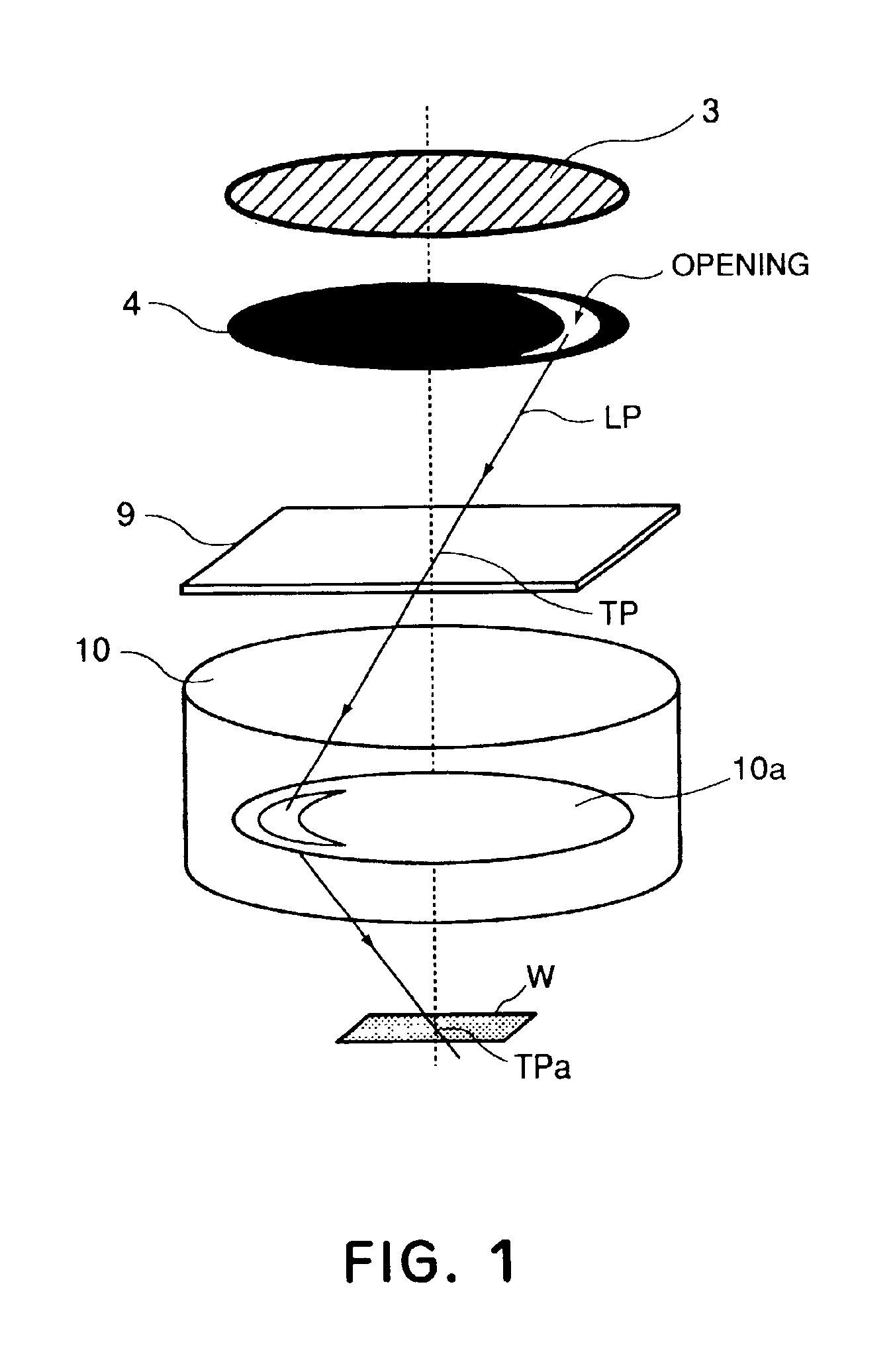
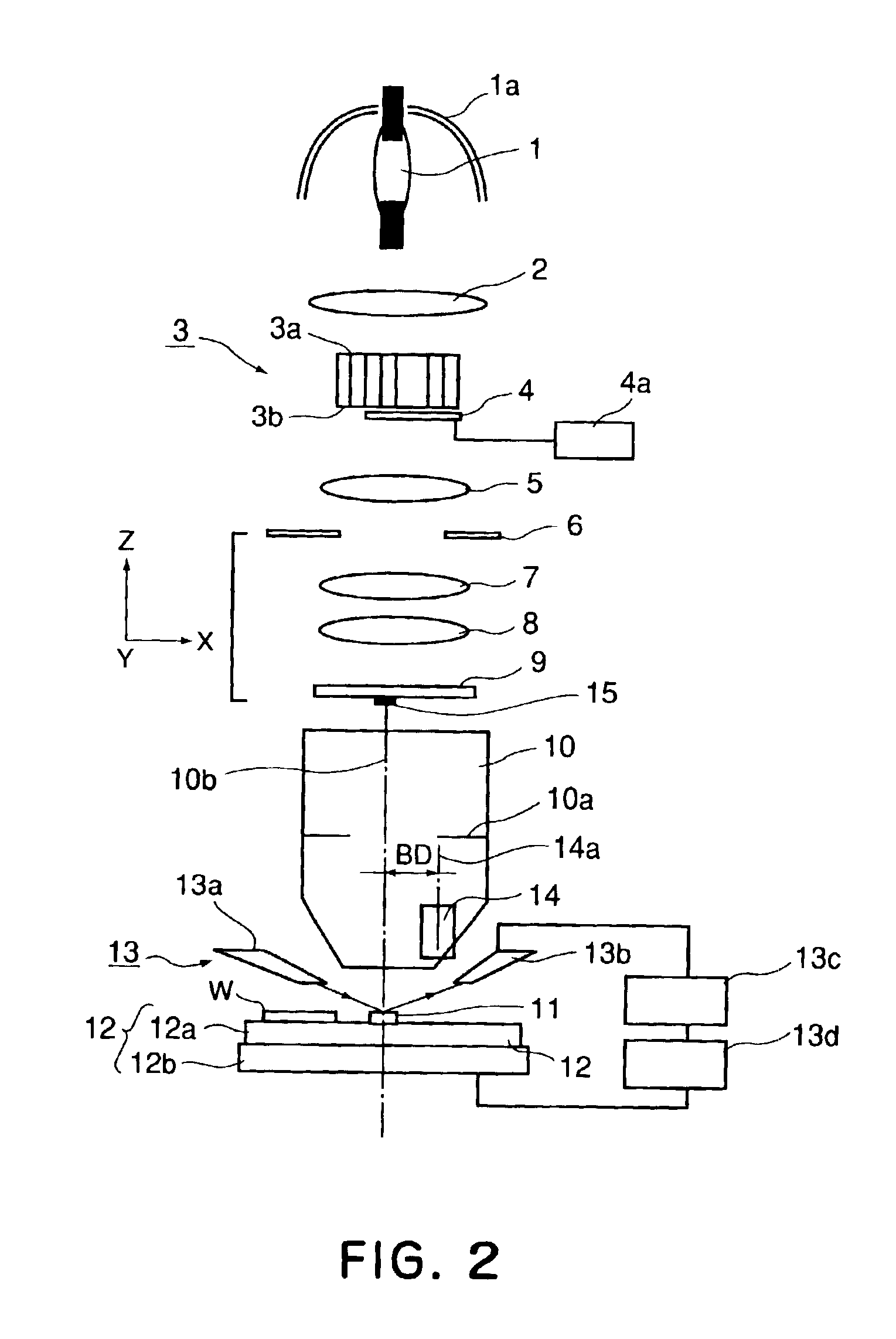
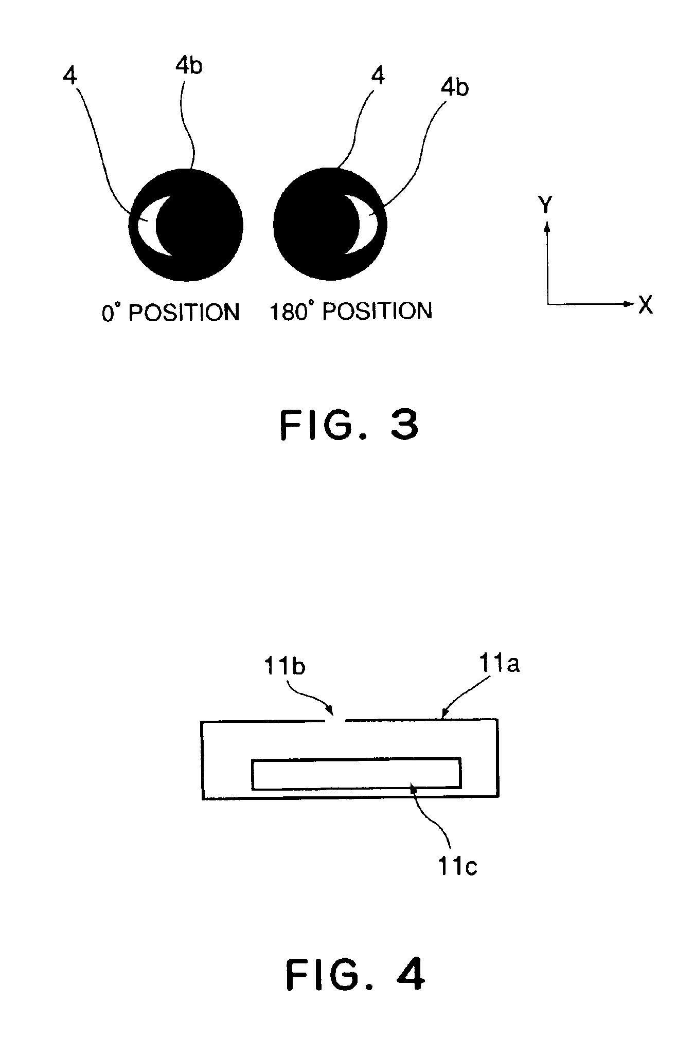
[0041]In the present invention, an effective light source and a test pattern are optimized so as to determine the region for light which is going to pass through a pupil plane of a projection optical system, with respect to a particular Zernike term (coefficient) and, by measuring a positional deviation of the test pattern formed by that light, the Zernike coefficient is calculated.
[0042]Before describing preferred embodiments of the present invention, how to obtain Zernike coefficients will be explained.
[0043]Several problems have been pointed out in regard to the method of calculating Zernike coefficients by measuring positional deviations of plural pattern images formed through a projection lens. Since the Zernike polynomial is an orthogonal polynomial, Zernike terms (coefficients) themselves do not affect each other. Namely, Zernike coefficients can be calculated indepe...
PUM
 Abstract
Description
Claims
Application Information