Sonar Mount

Active Publication Date: 2011-03-24
BRADLEY REASON
View PDF4 Cites 2 Cited by
  • Summary
  • Abstract
  • Description
  • Claims
  • Application Information

AI Technical Summary

Benefits of technology

[0006]An embodiment of the invention provides a sonar mount that allows repeatable, accurate and precise alignment of a sonar head to a boat. A tilt mechanism allows the sonar head to be lifted to a position that is substantially parallel to the boat's deck, thus facilitating pla

Problems solved by technology

This introduces many problems with regard to recalibrating the sonar head to the boat when it is replaced.
This is further complicated by the fact that it is desirable to have a “break away” method o

Method used


Image

  • Sonar Mount
  • Sonar Mount
  • Sonar Mount

Examples


Example

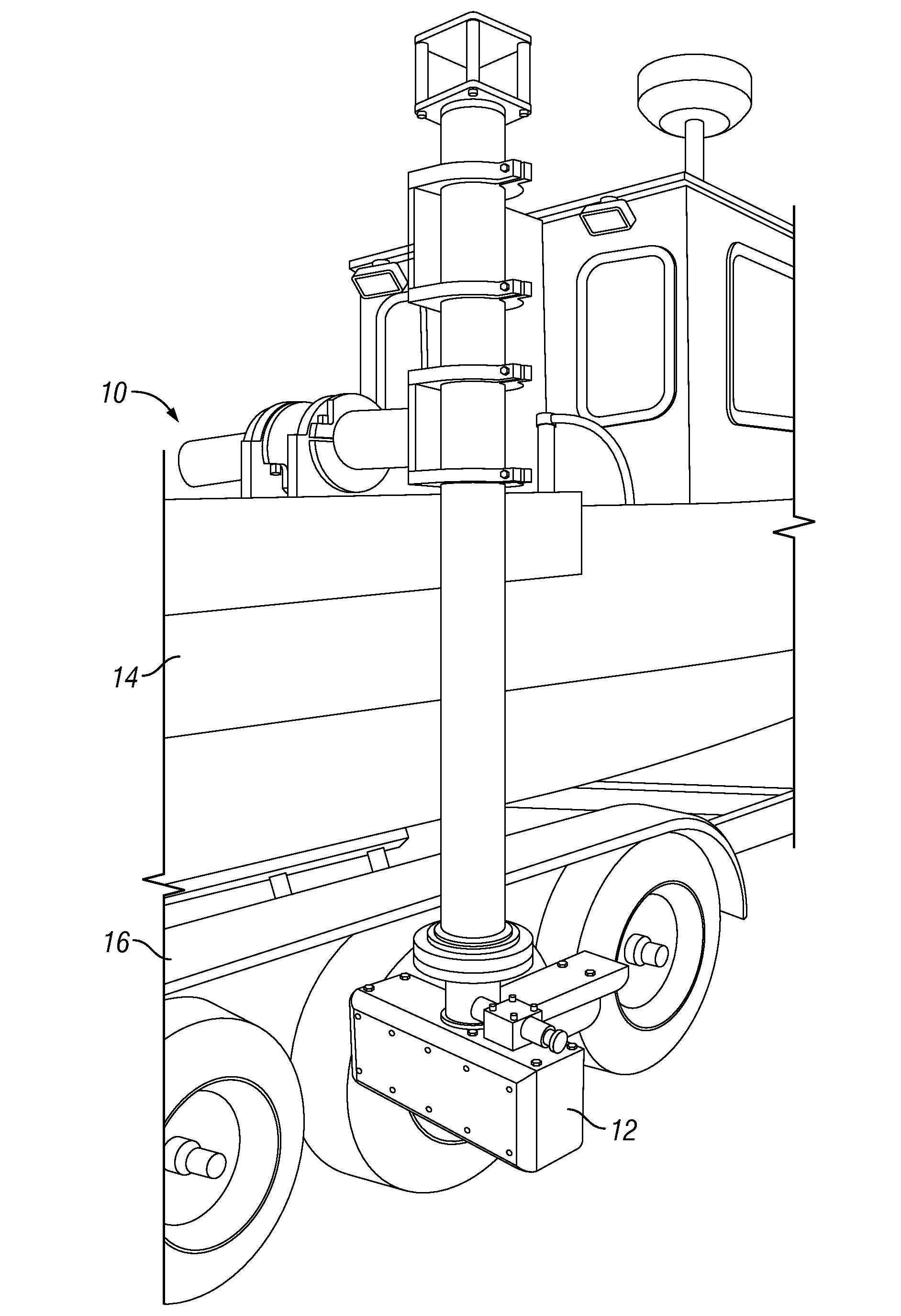
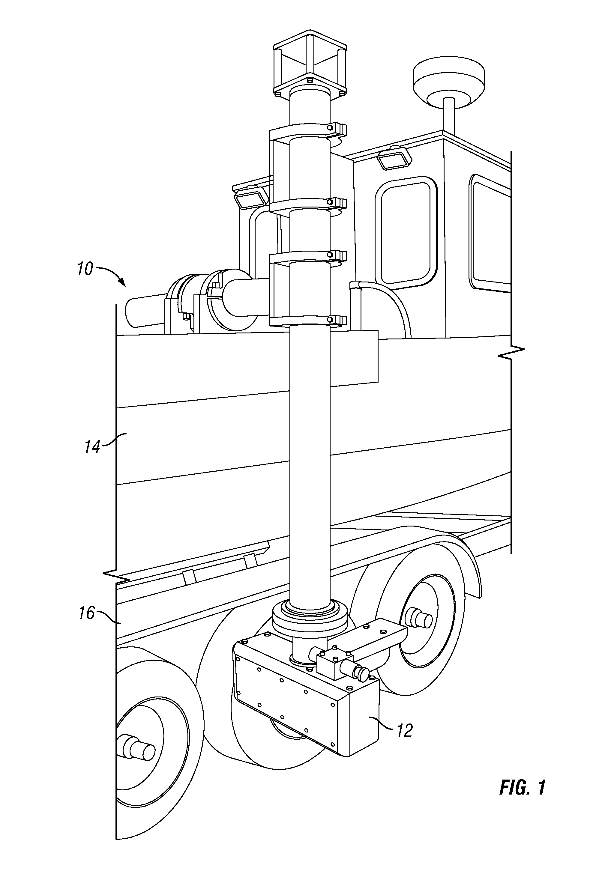
[0015]FIG. 1 is a perspective view of a sonar mount affixed to a boat according to the invention. In FIG. 1, a boat 14 rests upon a trailer 16. A sonar head unit 12 is attached to an end of a sonar mount 10, the sonar mount attached to the deck of the boat. An embodiment of the invention provides a sonar mount, as shown in FIG. 1, that is readily adjusted for a precise and accurate alignment relative to the boat; and that is tiltable about an axis of rotation to allow the sonar head to be elevated when the boat is on a trailer, for example, and to be readily lowered into an operable position when the boat is in the water. The sonar mount may also be tilted to a vertical position and serve as an antenna mast (discussed below).

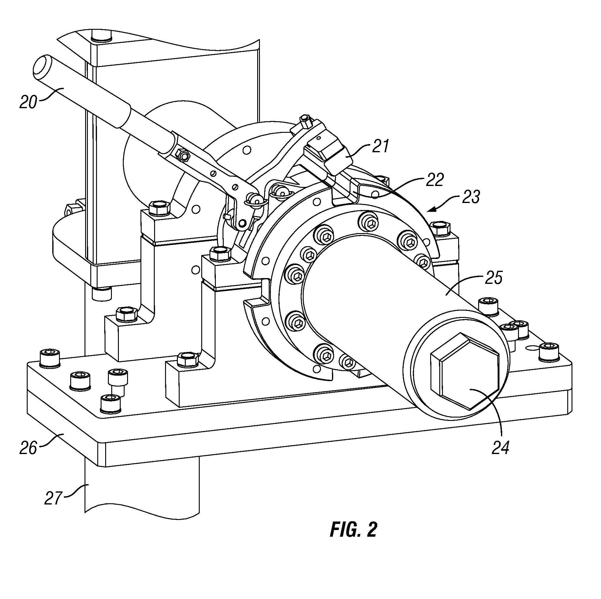
[0016]FIG. 2 is a perspective view of a sonar mount showing a clamp assembly according to the invention. In FIG. 2, the sonar mount is shown having a base plate 26 with clamp bolts. An embodiment of the invention provides a compound base plate (discussed below)....


PUM


Abstract

A sonar mount allows accurate and precise alignment of a sonar head to a boat. A tilt mechanism allows the sonar head to be lifted to a position that is substantially parallel to the boat's deck, thus facilitating placement of the boat on a trailer without the need to remove the sonar head from the boat.

Description

CROSS REFERENCE TO RELATED APPLICATIONS[0001]This application claims benefit of U.S. Provisional Application Ser. No. 61 / 243,750, filed Sep. 18, 2009, which is incorporated herein in its entirety by this reference thereto.BACKGROUND OF THE INVENTION[0002]1. Technical Field[0003]The invention relates to electronic equipment that is used in connection with boats and ships. More particularly, the invention relates to a sonar mount for use with a boat or ship.[0004]2. Description of the Background Art[0005]Sonar surveys are an important part of ship navigation, dredging compliance, finding underwater objects, maintaining safe waterways and mapping. The usefulness of sonar is directly affected by the accuracy and precision with which the sonar head is mounted to the boat or ship. Sonar equipment typically consists of an electronics unit, which is placed over the side of the boat for the operator to use, and a sonar head unit, which is placed below the waterline. Accurate and precise repe...

Claims


Application Information

Patent Timeline
IPC IPC(8): G10K11/00
CPCG10K11/006
Inventor BRADLEY, REASON
Owner BRADLEY REASON
Why Eureka
Try Eureka