Liquid phase-change brake

A brake, liquid phase technology, applied in the direction of brake type, mechanical equipment, etc., can solve the problems of complex device structure, troublesome replacement of friction elements, and high cost, and achieve the effects of simple manufacturing process, excellent braking performance, and good heat dissipation effect.

Inactive Publication Date: 2009-11-11
ZHEJIANG VIE SCI & TECH
View PDF0 Cites 33 Cited by
  • Summary
  • Abstract
  • Description
  • Claims
  • Application Information

AI Technical Summary

Problems solved by technology

However, the common disadvantages of the existing friction brakes are that the heat dissipation effect of the brake needs to be improved, the installation structure of the friction elements is complicated, the loss of the friction elements is large, and it is troublesome to replace the friction elements, which usually requires a complete set of replacements. The structure of the automatic gap adjustment device is complicated. The production process is complicated and the cost is high

Method used


Image

  • Liquid phase-change brake
  • Liquid phase-change brake
  • Liquid phase-change brake

Examples


Embodiment 1

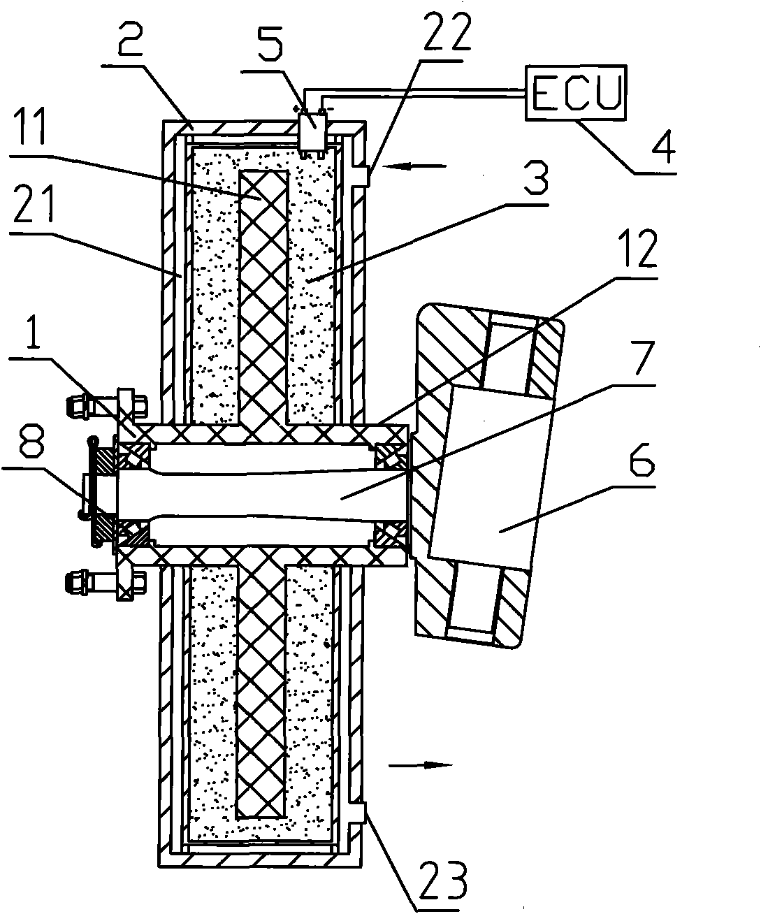
[0019] Embodiment one, such as figure 1 As shown, the liquid phase change brake includes a brake frame and a brake disc 1, the brake frame is a sealed box 2, the friction part 11 of the brake disc 1 passes through the inner space of the sealed box 2, The sealing box is a disc structure, and the middle part of the sealing box 2 extends to the shaft ring wall 12 of the brake disc, so that the friction part 1 is all in the sealing box 2, and the shaft of the sealing box and the brake disc The body ring wall junction is movable and sealed. The inner space of the sealed box 2 is filled with a reversible phase change liquid. Electrical signal socket 5 for electrical connection. A cooling channel 21 and a medium inlet 22 and a medium outlet 23 for communicating with an external cooling medium are also provided in the wall of the sealed box 2 . The medium inlet and medium outlet are respectively arranged on both sides of the sealed box. Among the figure, 6 is a steering knuckle, 7 ...

Embodiment 2

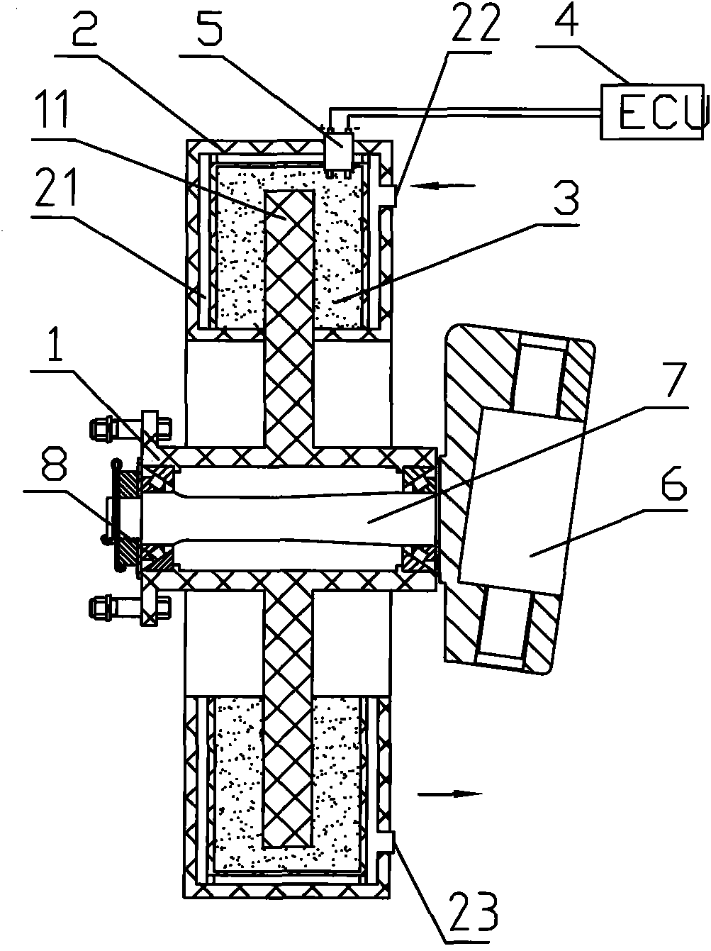
[0020] Embodiment two, such as figure 2 As shown, the liquid phase change brake includes a brake frame and a brake disc 1, the brake frame is a sealed box 2, the friction part 11 of the brake disc 1 passes through the inner space of the sealed box 2, The sealed box body is a disc structure, and the ring surface of the friction part 1 penetrates into the sealed box body 2 . The middle part of the sealing box 2 does not extend to the shaft ring wall of the brake disc, and the joint between the sealing box 2 and the friction part 1 of the brake disc is movable and sealed, and the inner space of the sealing box is filled with a reversible phase change liquid , in this embodiment, the reversible phase change fluid is electrorheological fluid 3 , and an electrical signal socket 5 electrically connected to an external control system 4 is also provided in the sealed box. A cooling channel 21 and a medium inlet 22 and a medium outlet 23 for communicating with an external cooling medi...

Embodiment 3

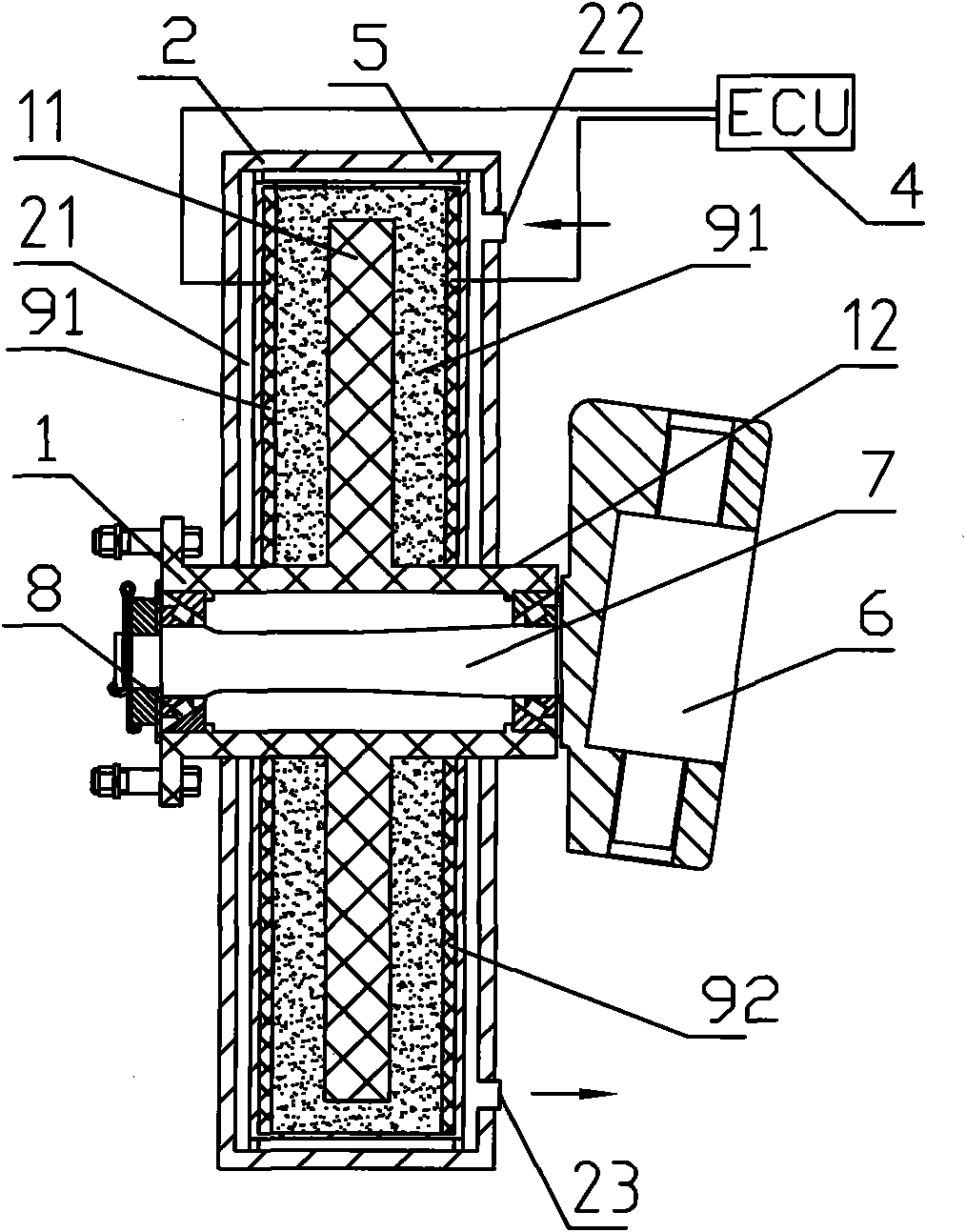
[0027] Embodiment 3. The difference between this embodiment and Embodiments 1 and 2 is that the reversible phase change liquid and its corresponding trigger device are different. In this embodiment, the reversible phase change liquid is a magneto-rheological liquid, and the trigger device is a magnetic Magnetic pole plate assembly on both sides of the rheological fluid. Such as image 3 As shown, the liquid phase change brake includes a brake frame and a brake disc 1, the brake frame is a sealed box 2, the friction part 11 of the brake disc 1 passes through the inner space of the sealed box 2, The sealing box is a disc structure, and the middle part of the sealing box 2 extends to the shaft ring wall 12 of the brake disc, so that the friction part 1 is all in the sealing box 2, and the shaft of the sealing box and the brake disc The body ring wall joint is movable and sealed, and the inner space of the sealed box 2 is filled with magnetorheological fluid 91, and there are als...


PUM


Abstract

The invention discloses a liquid phase-change brake comprising a brake rack and a brake disc. The brake rack is a sealed box. The friction part of the brake disc passes through the internal space of the sealed box. The joint between the friction part and the sealed box is moveably sealed. Reversible phase-change liquid is filled in the internal space of the sealed box. A triggering device which is electrically connected with an external control system and used for triggering the change of reversible phase-change liquid form is also arranged in the sealed box. The reversible phase-change liquid is electro-rheological liquid or magneto-rheological liquid. In the invention, the effect conversion that the reversible phase-change liquid changes from liquid state to solid state within milliseconds when an external trigger signal (electric field or magnetic field) exists and quickly restores to the original state when the external trigger signal is removed is applied in the brake, thus having the advantages of simple structure, excellent braking performance, good heat dissipation effect, low exhaustion of friction components, simple production technology and low cost.

Description

technical field [0001] The invention relates to a brake. Background technique [0002] The types of friction brakes mainly include block brakes, band brakes and disc brakes, which are mainly composed of three parts: brake frame, friction element and brake release device. Many brakes are also equipped with automatic gap adjustment devices, which are widely used in automobiles or Used in other mechanical equipment to control rotating parts. However, the common disadvantages of the existing friction brakes are that the heat dissipation effect of the brake needs to be improved, the installation structure of the friction elements is complicated, the loss of the friction elements is large, and it is troublesome to replace the friction elements, which usually requires a complete set of replacements. The structure of the automatic gap adjustment device is complicated. The manufacturing process is complicated and the cost is high. Contents of the invention [0003] The problem to...

Claims


Application Information

Patent Timeline
Patent Type & Authority Applications(China)
IPC IPC(8): F16D63/00
Inventor 李小攀钟焕祥童少荣姚玉丽
Owner ZHEJIANG VIE SCI & TECH
Why Eureka
Try Eureka