Method for analyzing digital interference fringe and device for detecting optical component surface shape

A technology of interference fringes and optical components, applied in the direction of optical devices, measuring devices, instruments, etc., can solve problems such as spectrum leakage, fence effect errors, etc., achieve the effects of suppressing errors, realizing real-time measurement, and improving estimation accuracy

Active Publication Date: 2010-02-17
CHINA NORTH IND NO 205 RES INST
View PDF1 Cites 29 Cited by
  • Summary
  • Abstract
  • Description
  • Claims
  • Application Information

AI Technical Summary

Problems solved by technology

[0004] The purpose of the present invention is to overcome the problems of spectrum leakage and fence effect introducing errors in the existing digital interference fringe Fourier analysis method without increasing the complexity of the device, thereby providing a digital holography-based object light wavefront The restored interference fringe analysis method and the optical element surface shape detection device realized by the analysis method, so as to realize high-precision, on-site and dynamic detection of the optical element surface shape

Method used


Image

  • Method for analyzing digital interference fringe and device for detecting optical component surface shape
  • Method for analyzing digital interference fringe and device for detecting optical component surface shape
  • Method for analyzing digital interference fringe and device for detecting optical component surface shape

Examples


Embodiment Construction

[0027] The present invention will be further described in detail below in conjunction with the accompanying drawings and preferred embodiments.

[0028] The digital interference fringe analysis method provided by the preferred embodiment of the present invention comprises the following steps:

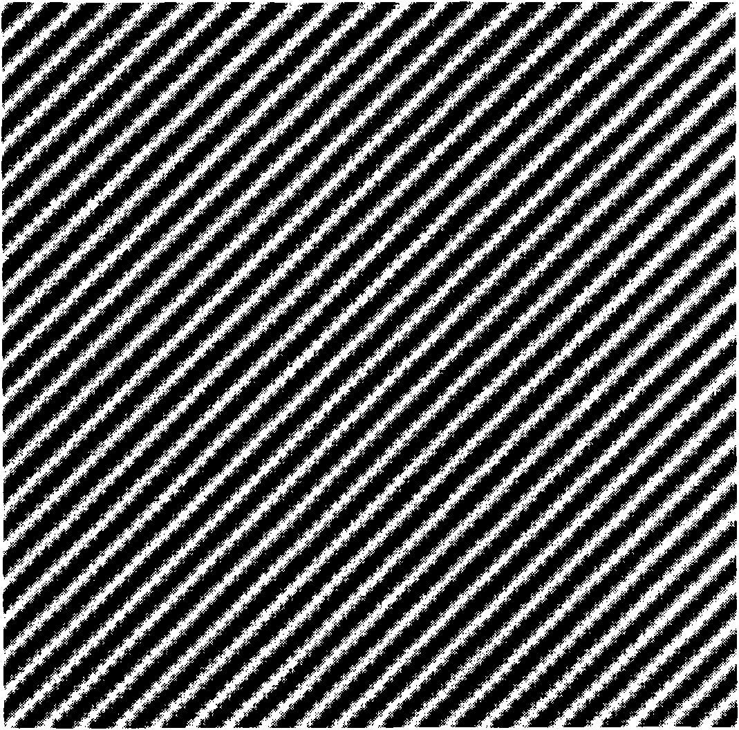
[0029] The first step is to use a solid-state imaging device, that is, a charge-coupled device (CCD) or a metal oxide semiconductor (CMOS) to obtain a first interference fringe image composed of the measured surface shape of the optical element and the surface shape of the standard optical element. Use a solid-state imaging device to obtain A first interference fringe image is converted into a digital interference fringe image by an A / D converter. In theory, the intensity distribution of general interference fringes can be expressed as:

[0030] g(x,y)=a(x,y)+b(x,y)cos(2πxf x0 +2πyf y0 +φ(x,y)) (1)

[0031] (1) where a(x, y) is the DC term of the fringe, b(x, y) is the intensity mod...


PUM


Abstract

The invention discloses a method for analyzing digital interference fringe and a device for detecting optical component surface shape. The main technical characteristic of the invention is that firstly a digital interference fringe image times a window function to expand the width of main lobe of interference fringe image spectrum and to inhibit side lobe of the interference fringe image spectrum;carrying out Fourier analysis on the digital interference fringe image; estimating space carrier frequency of the digital interference fringe by adopting an algorithmic method of a barycentric coordinates of a barycentric group; and the method is also used for the frequency shift of the digital interference fringe image, thus effectively inhibiting error to measurement by a hurdle effect. Besides, the device for detecting optical component surface shape constructed based on the method for analyzing digital interference fringe can carry out high-accuracy analysis on the interference fringe ofthe space carrier frequency when frequency sampling interval is not integral multiple, and has simple structure and good measuring instantaneity.

Description

technical field [0001] The invention relates to the technical field of optical precision measurement, in particular to a high-precision analysis method of digital interference fringes based on Fourier transform and an optical element surface shape detection device realized by the analysis method. Background technique [0002] In modern optical precision measurement and metrology, fringe analysis technology is involved in the fields of optical element surface shape detection, three-dimensional shape acquisition and surface roughness measurement. The fringes here can be interference fringes or projection fringes. For the analysis of interference fringes, two techniques are usually used, one is the phase shift technique, and the other is the Fourier transform analysis technique. In the phase shift technology, it is necessary to record the fringe multiple times, and it is necessary to ensure accurate phase shift and stable light intensity in each record, which brings great diffi...

Claims


Application Information

Patent Timeline
Patent Type & Authority Applications(China)
IPC IPC(8): G01B11/25
Inventor 范琦杨鸿儒黎高平陆琦
Owner CHINA NORTH IND NO 205 RES INST
Why Eureka
Try Eureka