Sealed water tank device of flush toilet

A flush toilet and sealing technology, which is applied in the water-saving field of the flush toilet tank, can solve the problems of unfavorable promotion, failure to save water, waste water, etc., and achieve the effect of saving water resources and less water consumption

Inactive Publication Date: 2010-06-09
杨健世
View PDF0 Cites 2 Cited by
  • Summary
  • Abstract
  • Description
  • Claims
  • Application Information

AI Technical Summary

Problems solved by technology

But because this water-saving device all is to control the water output of flushing water structurally to reach the purpose of saving water, and the flushing effect of this flush toilet is relatively poor, also can't wash away the excrement in the toilet once with high drainage sometimes, and Sometimes using low drainage during the second flushing will waste part of the water, which will fail to achieve the purpose of saving water
In essence, flush toilets rely on the difference between the water level in the water tank and the water level in the toilet to generate the momentum of the water to flush the urine and feces in the toilet. The momentum of the water is determined by the water pressure of the water tank. Due to the limited water drop, Therefore, the speed of flushing water is also limited. When the water pressure of the water tank is too low, no matter how much water is flushed, it cannot be flushed cleanly, and the cost of installing a booster device in the water tank is too high, which is not conducive to popularization.

Method used


Image

  • Sealed water tank device of flush toilet
  • Sealed water tank device of flush toilet
  • Sealed water tank device of flush toilet

Examples


Embodiment Construction

[0008] The embodiments of the present invention will be described in further detail below in conjunction with the accompanying drawings, but the present embodiments are not intended to limit the present invention, and any similar structures and similar changes of the present invention should be included in the protection scope of the present invention.

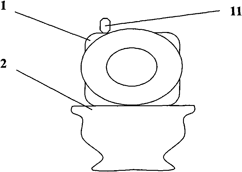
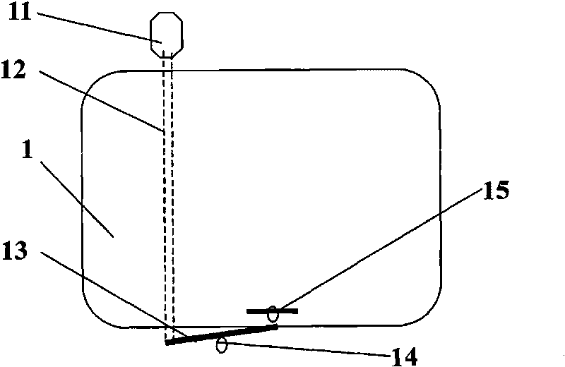
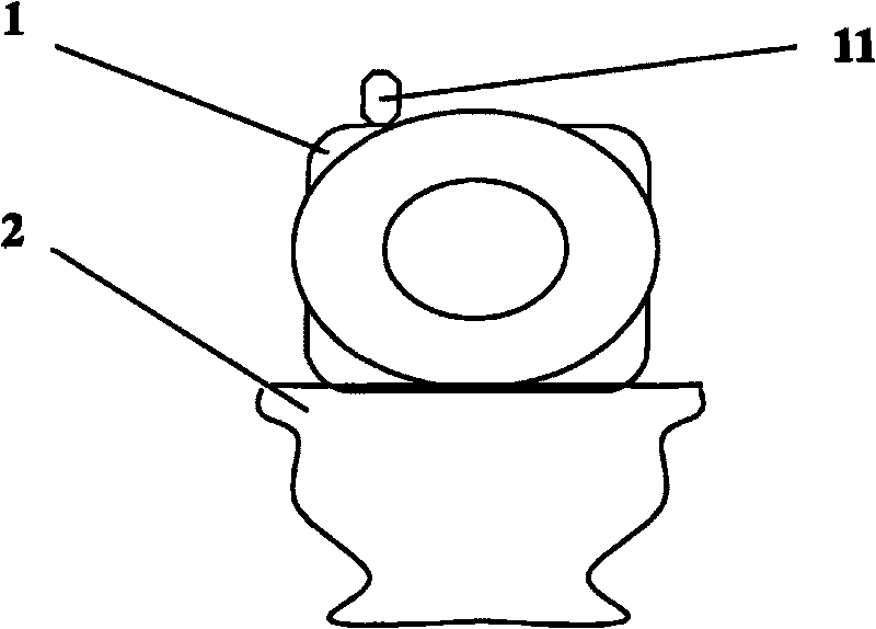
[0009] Depend on figure 1 , figure 2 As shown, a sealed water tank device for a flush toilet provided by the embodiment of the present invention includes a toilet 2 and a water tank 1. The water tank is provided with a water inlet valve for controlling the water inlet of the water tank and a flush valve for controlling the water outlet of the water tank. The water inlet valve Connect the tap water pipe, the flush valve is connected to the toilet through a water outlet pipe, and a flush valve switch assembly connected with the flush valve is arranged outside the water tank. It is characterized in that: the water tank is a clos...


PUM


Abstract

The invention discloses a sealed water tank device of a flush toilet, which relates to the technical field of water saving and solves the technical problem of the water saving of the flush toilet. The sealed water tank device comprises a flush toilet and a water tank, wherein the water tank is internally provided with a water inlet valve controlling the water inlet of the water tank and a flushing valve controlling the water outlet of the water tank, the water inlet valve is connected with a tap water pipe, the flushing valve is connected to the flush toilet through a water outlet pipe, and the outer part of the water tank is provided with a flushing valve switch assembly connected with the flushing valve. The sealed water tank device is characterized in that the water tank is a closed container, the flushing valve switch assembly comprises a control handle, a top rod, a flushing valve, a transmission arm and a transmission arm bracket, wherein the upper end of the top rod is connected with the control handle and the top rod is positioned at the rear part of the water tank, the flushing valve is positioned at the bottom of the water tank, two ends of the transmission arm are respectively connected with the lower end of the top rod and the bottom of the flushing valve, and the transmission arm bracket is positioned in the middle of the transmission arm. The invention has the characteristics of water saving, low cost, high water pressure, good flushing effect and convenient and labor-saving operation.

Description

technical field [0001] The invention relates to water-saving technology, in particular to a water-saving technology for a flush toilet water tank. Background technique [0002] At present, the flush toilets used in daily life are mainly composed of water tanks and toilets. Water-saving devices are also installed in the water tanks of many flush toilets. Discharge, for example, use a low drainage volume of about 3 liters when flushing urine, and use a large drainage volume of about 6 liters when flushing feces. But because this water-saving device all is to reach the purpose of water-saving by structurally controlling the output of flushing water, and the flushing effect of this flush toilet is relatively poor, sometimes also can't wash away the feces in the toilet once with high drainage, and Sometimes using low drainage during secondary flushing also wastes part of the water, which fails to achieve the purpose of saving water. In essence, flush toilets rely on the differe...

Claims


Application Information

Patent Timeline
Patent Type & Authority Applications(China)
IPC IPC(8): E03D1/00E03D3/10E03D5/09
Inventor 杨健世
Owner 杨健世
Why Eureka
Try Eureka