Automatic drainage control device of toilet bowl

A technology of automatic drainage and control device, applied in the field of sanitary ware, can solve the problems of insensitivity, easy damage, inconvenience for users and managers, etc., and achieves the effects of reliable action, convenient use, and avoiding high costs

Inactive Publication Date: 2011-01-19
陈焕忠
View PDF0 Cites 0 Cited by
  • Summary
  • Abstract
  • Description
  • Claims
  • Application Information

AI Technical Summary

Problems solved by technology

[0002] At present, most of the drainage of the toilet adopts a manual button. When using it, you need to press the button with your finger to flush, which is neither convenient nor hygienic.
Especially in public places, some people forget or do not want to press the button to flush water after use, which makes the sanitary condition of toilets in public places very poor and brings inconvenience to users and managers
For this reason, some toilets use electromagnetic induction electric drainage control devices to realize automatic flushing, but the cost is high, and the electromagnetic induction devices and electric devices are easily damaged or insensitive due to the humid environment.

Method used


Image

  • Automatic drainage control device of toilet bowl
  • Automatic drainage control device of toilet bowl
  • Automatic drainage control device of toilet bowl

Examples


Embodiment 1

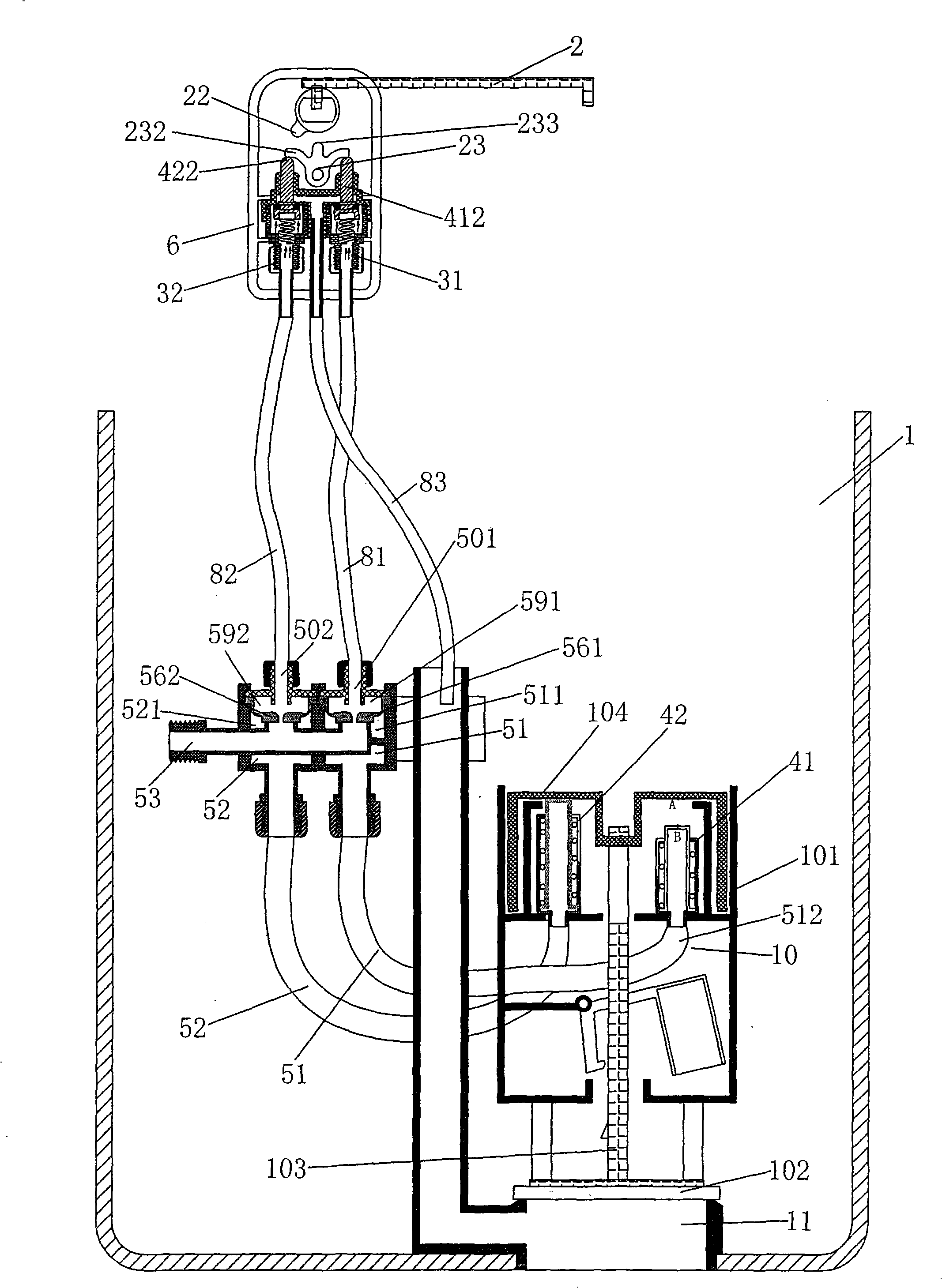
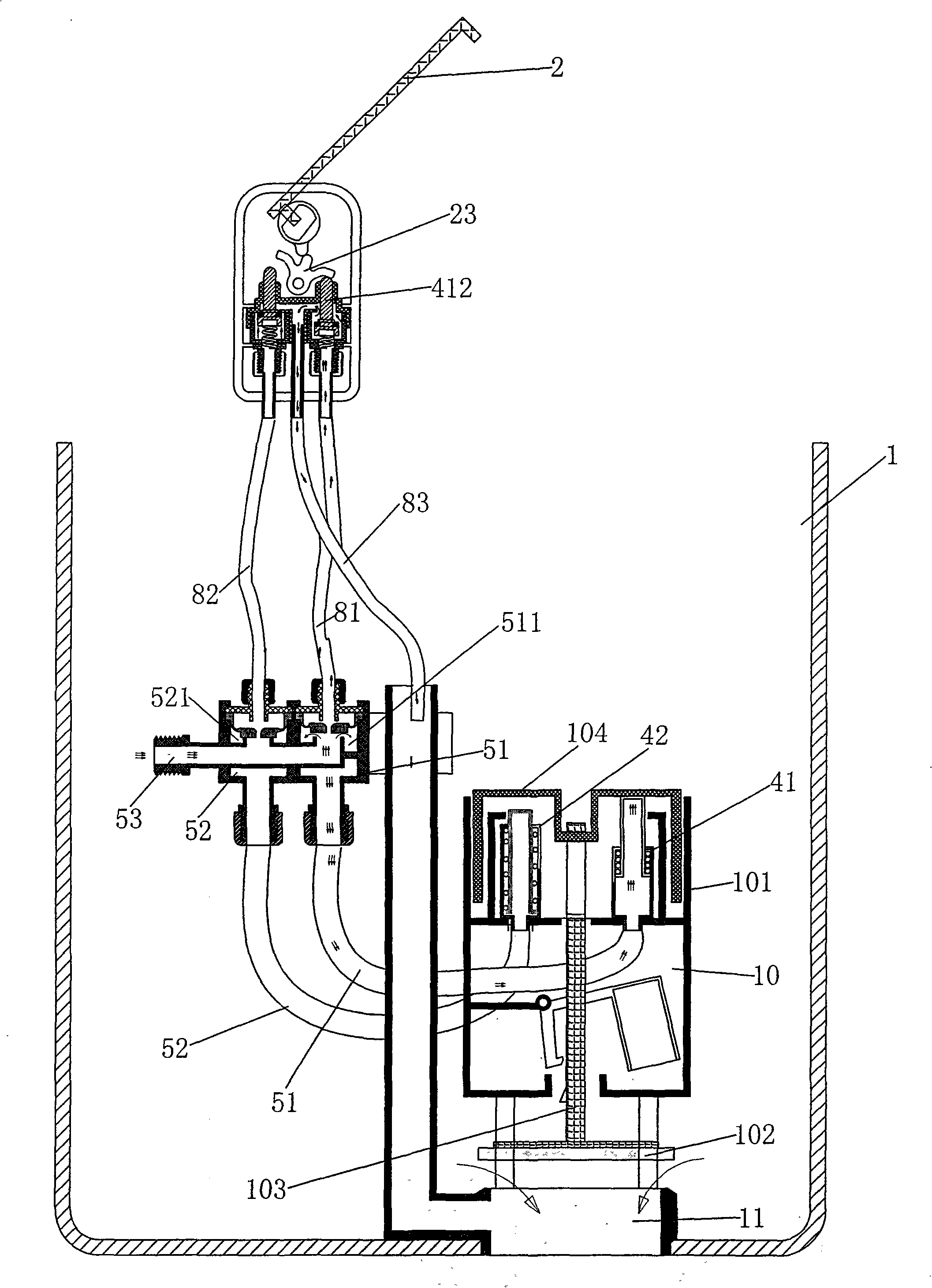
[0033] figure 1 , Figure 5 The shown toilet automatic drainage control device includes a cover plate 2 and a water tank 1, the cover plate 2 is provided with a rotating shaft 21, the water tank is provided with a drain port 11, a drain valve 10, and the drain valve is provided with a valve wall 101, a valve cover sheet 102, The valve cover lifting rod 103, the valve cover 102 is fixedly connected with the valve cover lifting rod 103, and the upper end of the valve cover lifting rod 103 is also connected with a transmission horizontal piece 104; figure 1 , Figure 9 , Figure 10 As shown, a first hydraulic cylinder 41 and a second hydraulic cylinder 42 are also provided in the water tank. A first piston rod 412 can be axially moved in the first hydraulic cylinder 41, and a first piston rod 412 can be installed in the second hydraulic cylinder 42. A second piston rod 422 is installed axially movable, and both the first piston rod and the second piston rod are located below t...

Embodiment 2

[0050] The structural principle and working process of the second embodiment are basically the same as those of the first embodiment, except that the structural form is slightly changed.

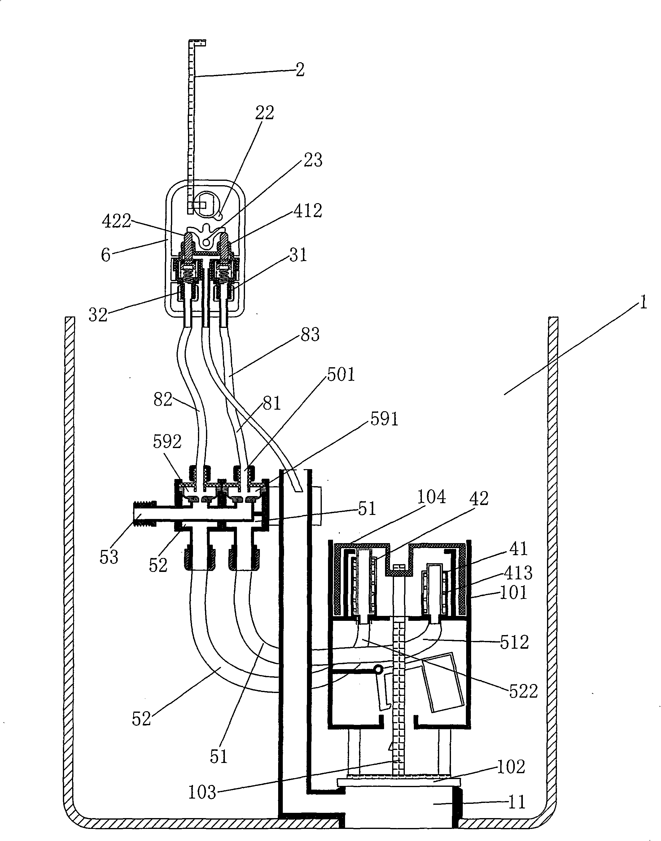
[0051] Figure 12 As shown, in Embodiment 2, the principle of the transmission structure of the cover plate, the first pressure relief valve, and the second pressure relief valve is the same as that of Embodiment 1, but the trident transmission block is in the shape of an inverted T.

[0052] Figure 14 , Figure 15 As shown, the first rubber pad 561 and the second rubber pad 562 in the second embodiment are flat, and the first small channel 571 between the first water pipe 551 and the first pressure chamber 591 is arranged beside the first water pipe 551 On the side, the second small channel 572 between the second water pipe 552 and the second pressure chamber 592 is arranged on the side of the second water pipe 552 . The front end 511 of the first water outlet channel is sleeved in the ...


PUM


Abstract

The invention discloses an automatic drainage control device of a toilet bowl, wherein a first hydraulic cylinder, a second hydraulic cylinder, a first piston rod and a second piston rod are arranged in a water tank thereof; a transmission mechanism being capable of driving a valve cover plate to move up and down is arranged between the two piston rods and the valve cover plate; a first running water pipe, a first water exit, a second running water pipe and a second water exit are also arranged; the back end of the first water exit is communicated with the cavity of the first hydraulic cylinder; the back end of the second water exit is communicated with the cavity of the second hydraulic cylinder; the water outlet of the first running water pipe is also covered by a first rubber cushion; the water outlet of the second running water pipe is also covered by a second rubber cushion; a first pressure chamber is formed above the first rubber cushion; a second pressure chamber is formed above the second rubber cushion; the cover board is also coaxially and fixedly connected with a shifting block; a three-pronged transmission block is rotatablely arranged beside the shifting block; and afirst pressure relief valve and a second pressure relief valve are arranged beside the three-pronged transmission block. The automatic drainage control device can realize automatic flush without pressing a push button.

Description

technical field [0001] The invention belongs to the technical field of sanitary ware, and in particular relates to an automatic drainage control device for a toilet. Background technique [0002] At present, most of the drains of toilets adopt manual buttons, which need to be pressed with fingers to flush water, which is inconvenient and unhygienic. Especially in public places, some people forget or do not want to press the button to flush water after using, which makes the sanitary condition of toilets in public places very poor, which brings inconvenience to users and managers. For this reason, some toilets adopt electromagnetic induction electric drainage control devices to realize automatic flushing, but the cost is high, and the electromagnetic induction devices and electric devices are easily damaged or insensitive due to being in a humid environment. Contents of the invention [0003] The object of the present invention is to overcome the above disadvantages and pr...

Claims


Application Information

Patent Timeline
Patent Type & Authority Patents(China)
IPC IPC(8): E03D5/04E03D1/34
Inventor 陈焕忠
Owner 陈焕忠
Why Eureka
Try Eureka