

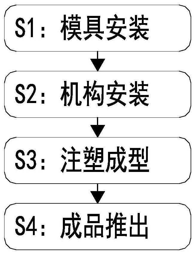
Electric meter box transparent plastic shell injection molding method
A technology of injection molding and transparent plastic, applied in the field of plastic injection molding, can solve the problems of easy sticking, damage to the transparent plastic shell, inconvenience, etc., and achieve the effect of easy replacement of molds
- Summary
- Abstract
- Description
- Claims
- Application Information
AI Technical Summary
Problems solved by technology
Method used
Image

Examples
Embodiment Construction
[0038] The embodiments of the present invention will be described in detail below with reference to the accompanying drawings, but the present invention can be implemented in many different ways defined and covered by the claims.
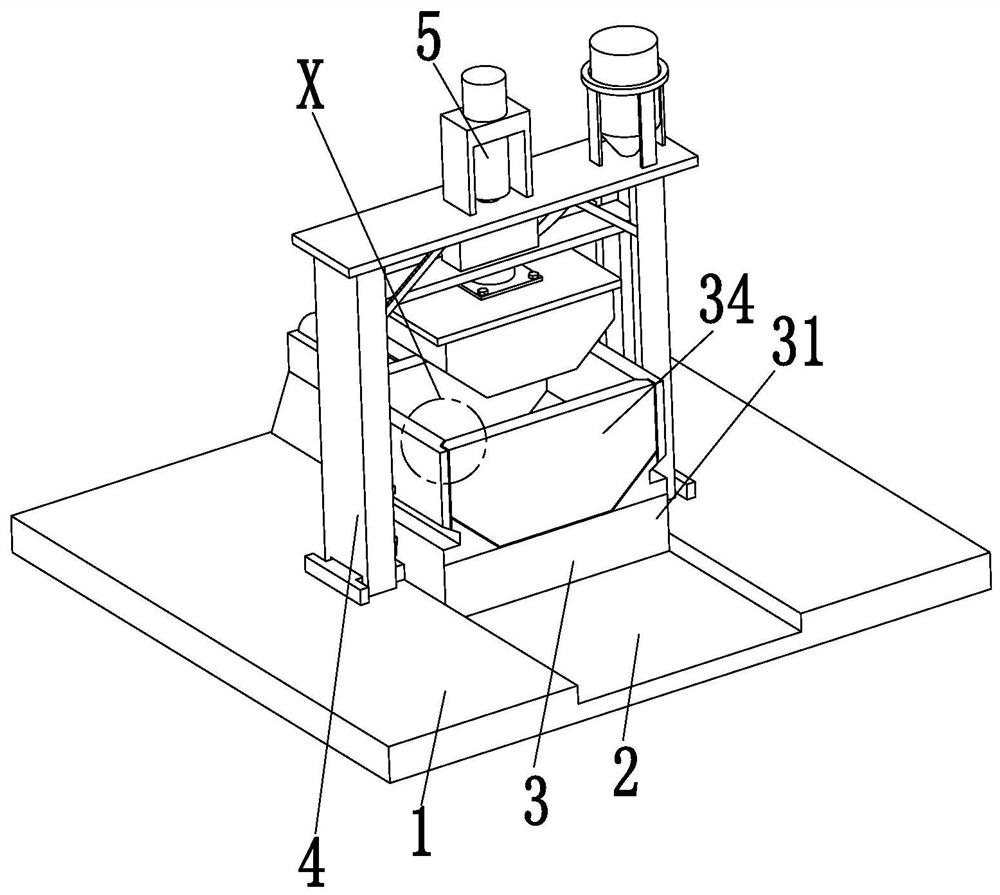
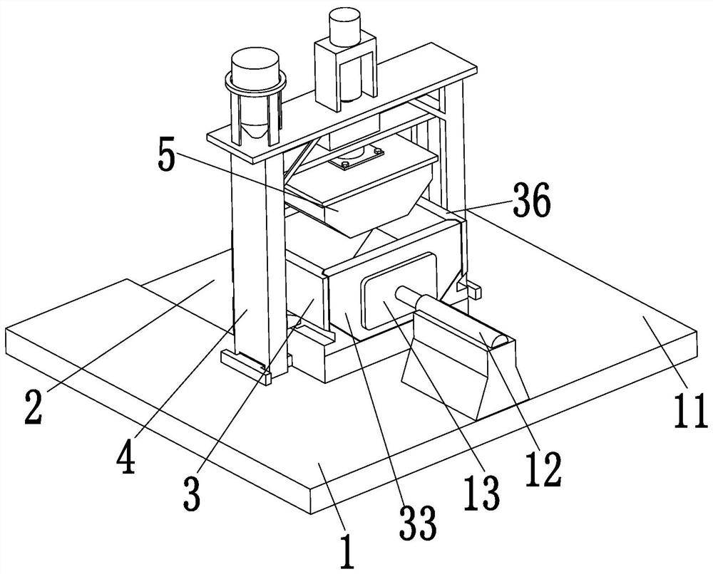
[0039] Such as Figure 1 to Figure 10 As shown, a method for injection molding of a transparent plastic shell of an electric meter box, the injection molding method adopts the following preparation machine: the machine includes a fixed base 1, a sliding groove 2, a molding device 3, a supporting base plate 4 and an injection molding device 5, the described The front side of the upper end of the fixed base 1 is provided with a sliding groove 2, and a molding device 3 is slidably arranged in the sliding groove 2. A support base plate 4 is symmetrically arranged on the left and right sides of the upper end of the fixed base 1, and an injection molding device 5 is installed on the upper end of the support base plate 4. .
[0040] The fixed base 1 include...
PUM
 Abstract
Description
Claims
Application Information