A fully automatic pipe punching machine

A punching machine, fully automatic technology, applied in the field of machinery, can solve the problems of low punching efficiency, reduced work efficiency, wide area, etc., and achieve the effect of effective feeding effect.

Active Publication Date: 2019-03-05
嘉兴市远超自动化设备有限公司
View PDF9 Cites 0 Cited by
  • Summary
  • Abstract
  • Description
  • Claims
  • Application Information

AI Technical Summary

Problems solved by technology

[0002] In modern life, pipes are used more and more widely, and these pipes usually need to be punched in the process of processing. At present, there are not many automatic punching equipment for pipes on the market, and they are basically driven by multi-station cylinders. Positioning, cylinder advancement is difficult to ensure positioning accuracy, product cylinders of different lengths need to be repositioned, and the multi-station design is time-consuming and laborious when replacing products, which is not suitable for the current market situation of multi-variety and small-batch production. When punching holes on multiple sides, multiple clamping is required, which greatly reduces work efficiency and requires professional technicians to operate
However, when punching manually, the punching accuracy cannot be effectively guaranteed, the punching efficiency is low, the scrapping efficiency is high during the punching process, and the safety factor is low, the labor intensity is high, and the punching noise is large, which is not conducive to protecting workers. Physical and mental health, and the current punching equipment is basically relatively large in size, occupies a large area, and is relatively cumbersome for installation and handling. Equipment for multi-faceted continuous processing of various tube shapes

Method used


Image

  • A fully automatic pipe punching machine
  • A fully automatic pipe punching machine
  • A fully automatic pipe punching machine

Examples


Embodiment Construction

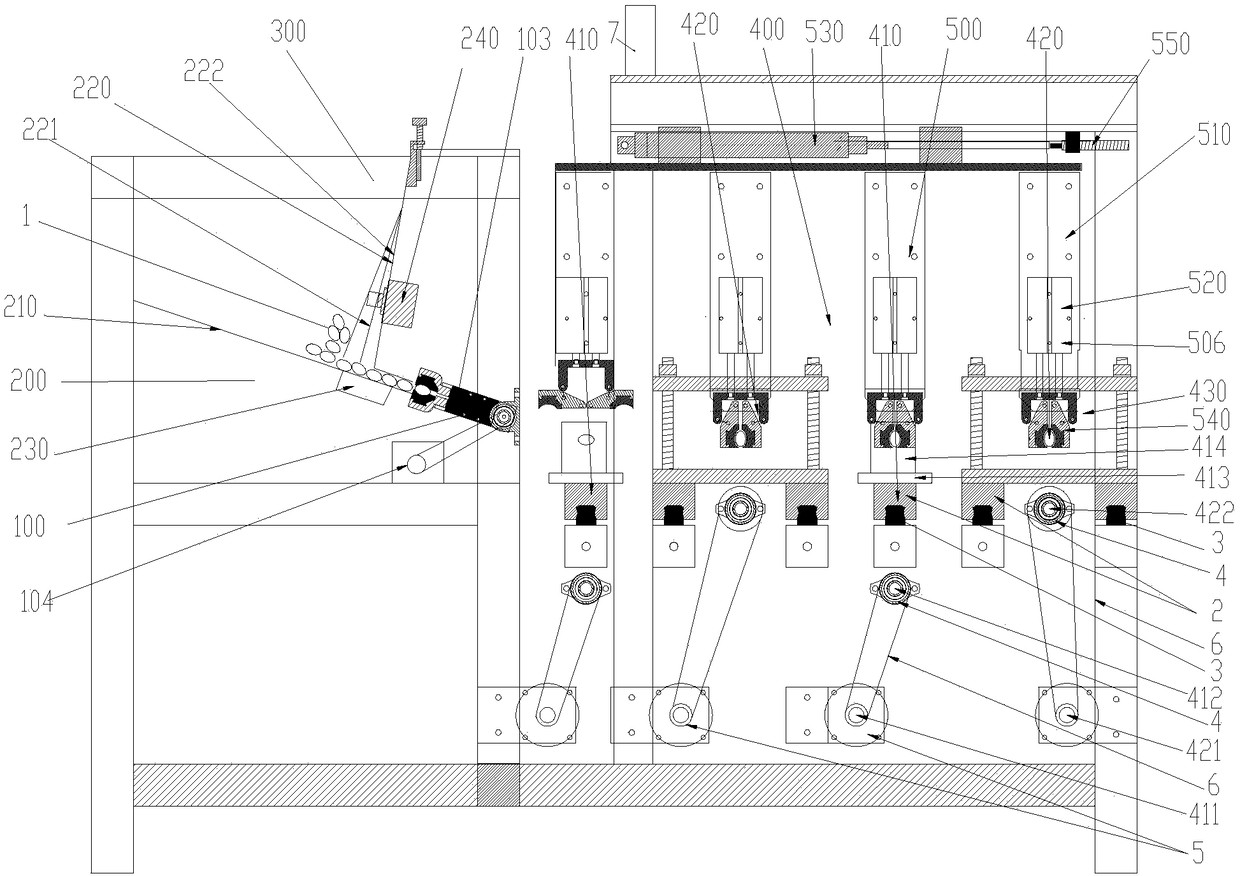
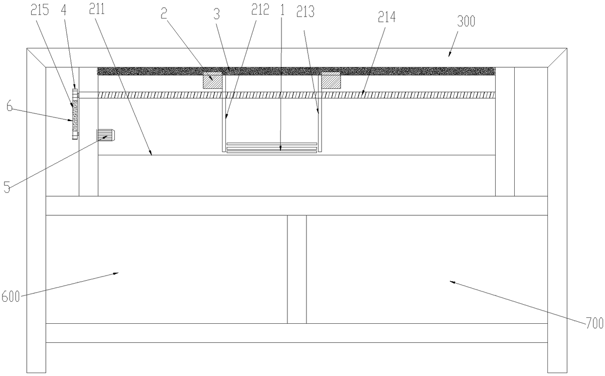
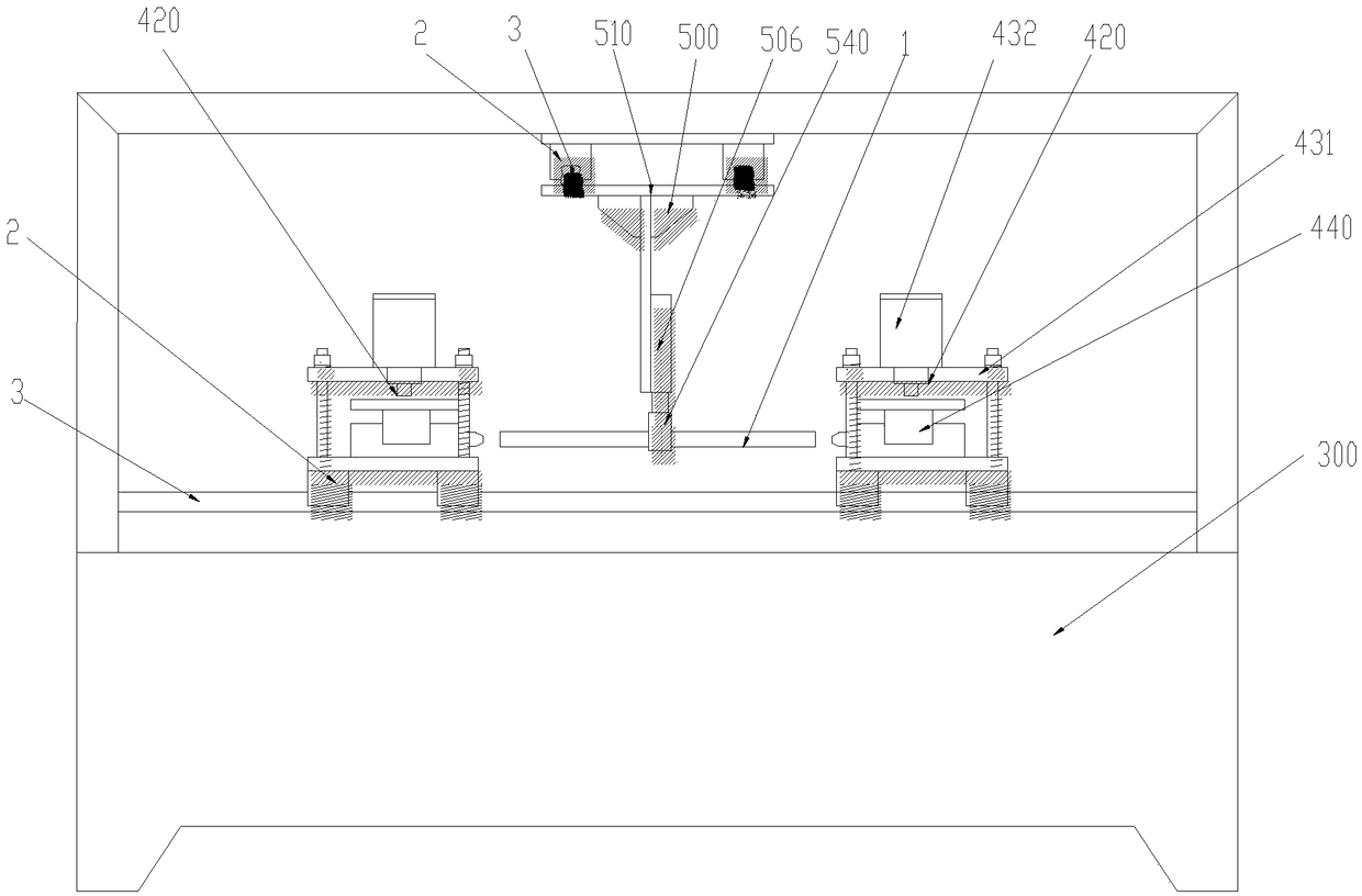
[0034] Such as Figure 1~6As shown, a fully automatic pipe punching machine includes a frame 300, a discharge mechanism 200 arranged on the frame 300, a turning mechanism 100 for moving the pipe on the discharging mechanism 200, and the turning mechanism 100 is used in conjunction with The forming mechanism 400 for punching and forming the pipe material, the conveying mechanism 500 for moving the pipe material on the forming mechanism 400, the hydraulic control system 600 provided on the frame 300 to provide power for the forming mechanism, and the electrical control system for controlling each mechanism. Control system 700, the pipes are arranged through the discharging mechanism 200, the pipes are moved from the discharging mechanism 200 to the forming mechanism 400 through the turning mechanism 100 for stamping and forming, and the processed pipes are sequentially forwarded on the forming mechanism 400 through the conveying mechanism 500 Mobile molding; the discharge mechan...


PUM


Abstract

The invention provides a full-automatic pipe punching machine. The full-automatic pipe punching machine comprises a rack, a feeding mechanism arranged on the rack, an overturning mechanism for moving pipes on the feeding mechanism, a forming mechanism conducting punching forming on the pipes, a conveying mechanism for moving the pipes on the forming mechanism, a hydraulic control system arranged on the rack and used for supplying power to the forming mechanism, and an electrical control system controlling the various mechanisms, wherein the forming mechanism is used in cooperation with the overturning mechanism. The pipes are arranged through the feeding mechanism, the pipes are moved to the forming mechanism from the feeding mechanism through the overturning mechanism to be subjected to punching forming, and the conveying mechanism is used for sequentially moving the machined pipes on the forming mechanism forwards for forming. A servo motor and a stepping motor are adopted for conducting accurate position control, various kinds of input and output control procedures in the machining process are conducted through a PLC, a user only needs to set product parameters on the touch screen, the system can automatically generate data of various functional devices, the motion stable precision is high, and the hydraulic punching noise is low.

Description

technical field [0001] The invention relates to the field of machinery, in particular to a fully automatic pipe punching machine. Background technique [0002] In modern life, pipes are used more and more widely, and these pipes usually need to be punched in the process of processing. At present, there are not many automatic punching equipment for pipes on the market, and they are basically driven by multi-station cylinders. Positioning, cylinder advancement is difficult to ensure positioning accuracy, product cylinders of different lengths need to be repositioned, and the multi-station design is time-consuming and laborious when replacing products, which is not suitable for the current market situation of multi-variety and small-batch production. When punching holes on multiple sides, multiple clamping is required, which greatly reduces work efficiency and requires professional technicians to operate. However, when punching manually, the punching accuracy cannot be effecti...

Claims


Application Information

Patent Timeline
Patent Type & Authority Patents(China)
IPC IPC(8): B21D28/28B21D28/34B21D43/00B21D43/20B21D43/02B21D43/04B21D43/10B21C51/00
CPCB21C51/00B21D28/28B21D28/34B21D43/006B21D43/02B21D43/026B21D43/04B21D43/105B21D43/20
Inventor 袁瑞军
Owner 嘉兴市远超自动化设备有限公司
Why Eureka
Try Eureka