Lubricant composition, expandable shaft, and steering system using the same
a technology of lubricant composition and expandable shaft, which is applied in the direction of mechanical equipment, couplings, transportation and packaging, etc., can solve the problems of inability to mount the expandable shaft, driver discomfort, and driver discomfort, and achieve good lubricating performance
Inactive Publication Date: 2007-09-13
JTEKT CORP
View PDF7 Cites 2 Cited by
- Summary
- Abstract
- Description
- Claims
- Application Information
AI Technical Summary
Benefits of technology
[0009] An object of the present invention is to provide a lubricant composition used for lubricating an expandable shaft to prevent stick-slip from occurring when a high surface pressure is applied thereto, thereby allowing to maintain a good lubricating performance consistently, an expandable shaft comprising a pair of shaft members filled with the lubricant composition, and a steering system using the expandable shaft as an intermediate shaft.
[0013] According to the present invention, the kinematic viscosity of the base oil is limited to 1500 mm2 / s or more at 40° C., and the polytetrafluoroethylene (PTFE) also serving as a solid lubricant is used as a thickener. Therefore, the lubricant composition is used for lubricating the expandable shaft, to make it difficult to cause oil film shortage when a high surface pressure is applied thereto as well as to make it possible to prevent stick-slip from occurring when the oil film shortage occurs. Further, since the kinematic viscosity of the base oil is limited to 13000 mm2 / s or less at 40° C., which also prevents a sliding load from being too high such as in a case where the expandable shaft is incorporated as an intermediate shaft into a column-type EPS while expanding and contracting the expandable shaft to change the distance between the steering shaft and the steering mechanism, whereby the workability in assembling the column-type EPS into an automobile is also improved.
Problems solved by technology
In this case, the expandable shaft cannot be assembled by inserting the male spline into the female spline if there is no clearance between the splines.
JP2001-50293A, however, both the shaft members are relatively displaced in a radial direction and a circumferential direction to produce a rattle sound, which makes a driver uncomfortable.
If normal grease is used for lubricating the expandable shaft, stick-slip due to oil film shortage occurs, which causes a new problem of making a driver uncomfortable, by a slip sound easily produced particularly when the steering wheel is returned.
Method used
View moreImage
Smart ImageViewing Examples
Examples
examples 1 to 5
[0044] Lubricant compositions in Examples 1 to 5 were prepared using poly-α-olein oils having kinematic viscosities of 1500 mm2 / s (Example 1), 2054 mm2 / s (Example 2), 5548 mm2 / s (Example 3), 7414 mm2 / s (Example 4), and 12500 mm2 / s (Example 5) at 40° C., respectively as base oils and PTFE as thickeners. Both the components were mixed such that the content of PTFE was 45 % by weight.
Login to View More PUM
| Property | Measurement | Unit |
|---|---|---|
| Percent by mass | aaaaa | aaaaa |
| Kinematic viscosity | aaaaa | aaaaa |
| Area | aaaaa | aaaaa |
Abstract
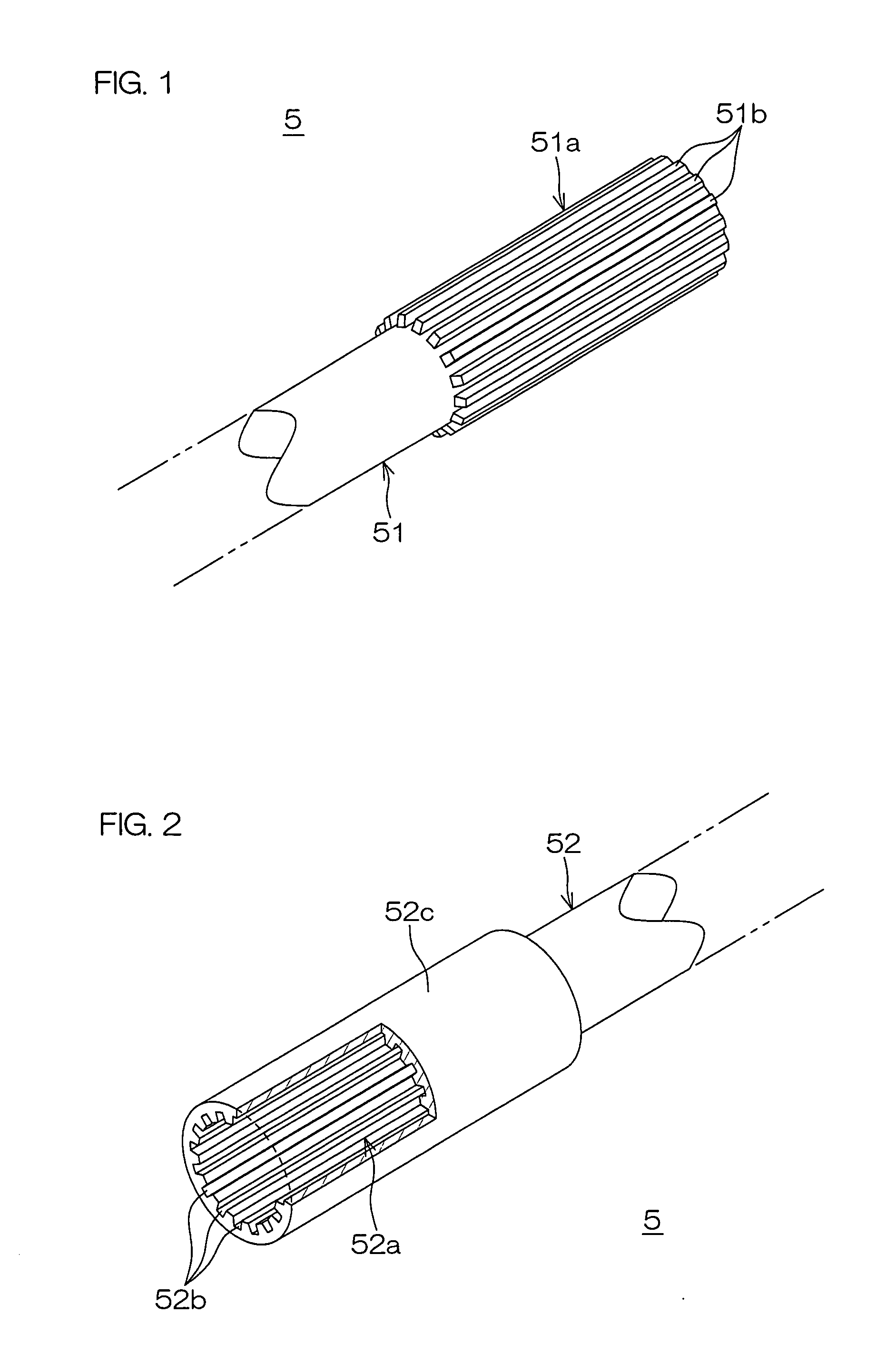
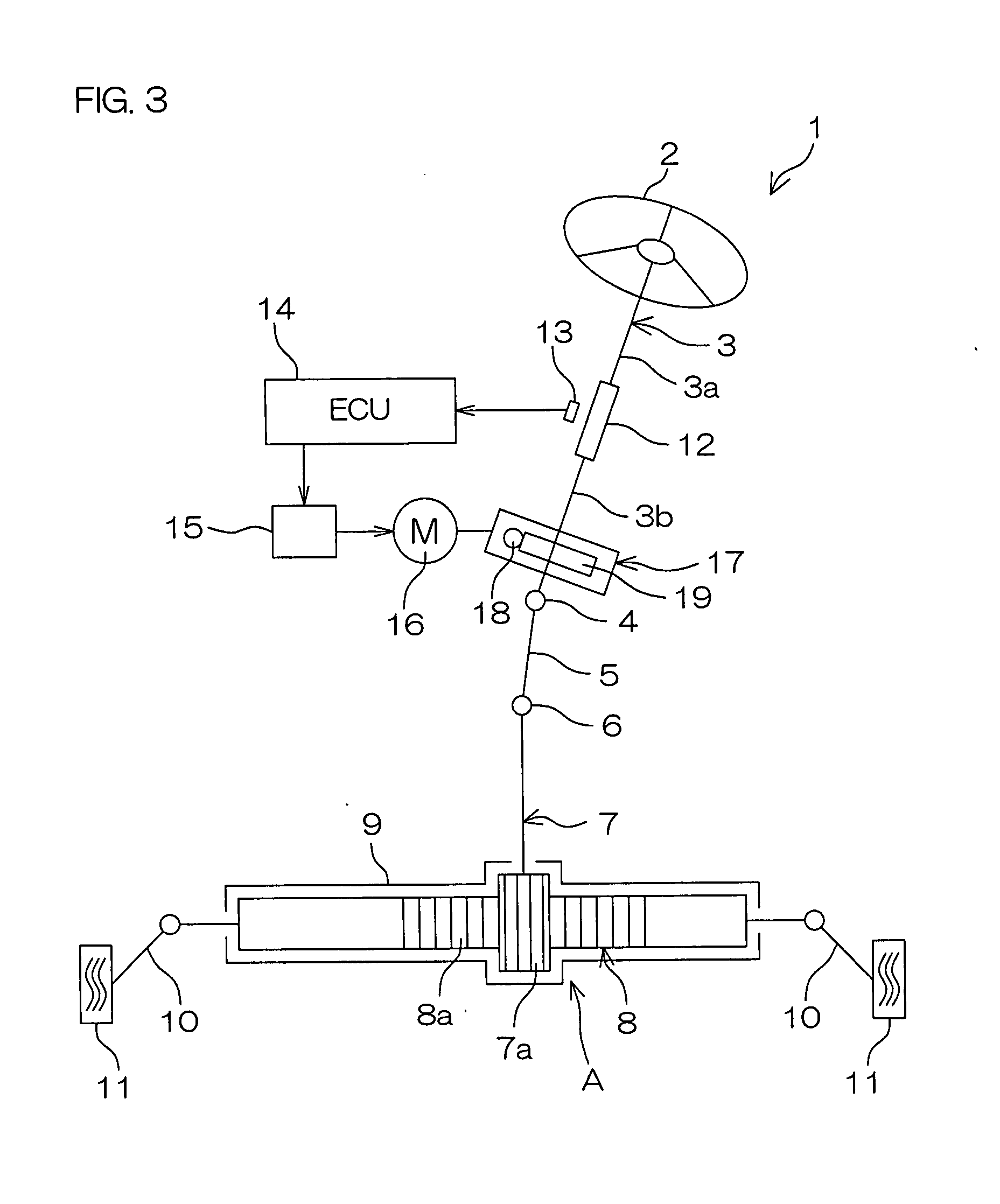
A lubricant composition contains a base oil having a kinematic viscosity of 1500 to 13000 mm2 / s (40° C.) and polytetrafluoroethylene serving as a thickener, and is used for lubricating an expandable shaft to prevent stick-slip from occurring when a high surface pressure is applied thereto, thereby allowing to maintain a good lubricating performance consistently. The expandable shaft 5 has a pair of shaft members 51 and 52 filled with the lubricant composition. In a steering system 1, the expandable shaft 5 is incorporated as an intermediate shaft into an area between a steering shaft 3 and a rack-and-pinion mechanism A.
Description
BACKGROUND OF THE INVENTION [0001] 1. Field of the Invention [0002] The present invention relates to a lubricant composition suited to lubricate an expandable shaft comprising a pair of shaft members axially expandable and contractible and coupled to each other to be integrally rotatable in a direction of rotation around its axis to fill an area between both the shaft members, the expandable shaft, and a steering system incorporating the expandable shaft. [0003] 2. Description of Related Art [0004] Examples of EPS (Electric Power Steering System) for automobiles include column-type EPS utilizing a rotary force of an electric motor provided on a column. In the column-type EPS, an expandable shaft comprising a pair of shaft members axially expandable and contractible and coupled to each other to be integrally rotatable in a direction of rotation around its axis has spread as an intermediate shaft for connecting a steering shaft connected to a steering wheel serving as a steering membe...
Claims
Login to View More Application Information
Patent Timeline
 IPC IPC(8): C10M119/22
CPCC10M119/22C10M169/02C10M2205/0285C10N2250/10C10N2220/022C10N2240/20C10M2213/0626C10N2020/02C10N2040/14C10N2050/10F16D3/06F16D2300/06
Inventor KASAHARA, FUMIAKIKAKUTANI, SATOSHIMINAGAWA, KAZUTO
Owner JTEKT CORP
Features
- R&D
- Intellectual Property
- Life Sciences
- Materials
- Tech Scout
- Unparalleled Data Quality
- Higher Quality Content
- 60% Fewer Hallucinations
Learn More Browse by: Latest US Patents, China's latest patents, Technical Efficacy Thesaurus, Application Domain, Technology Topic, Popular Technical Reports.
© 2025 PatSnap. All rights reserved.Legal|Privacy policy|Modern Slavery Act Transparency Statement|Sitemap|About US| Contact US: help@patsnap.com


