Fixed structure of pedal support

A pedal and structure technology, applied to the fixed structure of the pedal bracket, can solve the problems of increased number of parts, poor operability, temporary retention of stud bolt 06, etc., and achieve the effect of reducing the number and improving operability

Active Publication Date: 2012-12-26
HONDA MOTOR CO LTD
View PDF1 Cites 0 Cited by
  • Summary
  • Abstract
  • Description
  • Claims
  • Application Information

AI Technical Summary

Problems solved by technology

However, with such a configuration, temporary holding (positioning) by the stud bolts 06 cannot be performed when the pedal bracket 02 is assembled, so there is a possibility that operability may deteriorate.
[0007] In order to avoid the above-mentioned problems, the above-mentioned prior art adopts the mounting bracket 03 which can be attached and detached freely with respect to the pedal bracket 02. Since the mounting bracket 03 is provided, there is a problem that the number of parts increases.

Method used


Image

  • Fixed structure of pedal support
  • Fixed structure of pedal support
  • Fixed structure of pedal support

Examples


Embodiment Construction

[0036] Hereinafter, embodiments of the present invention will be described based on the drawings.

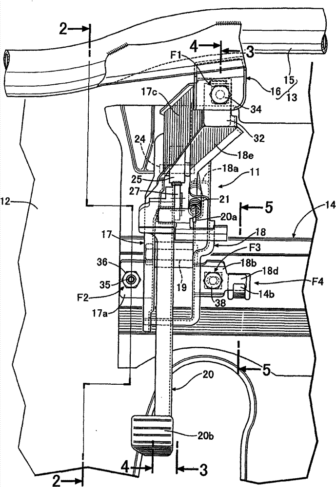
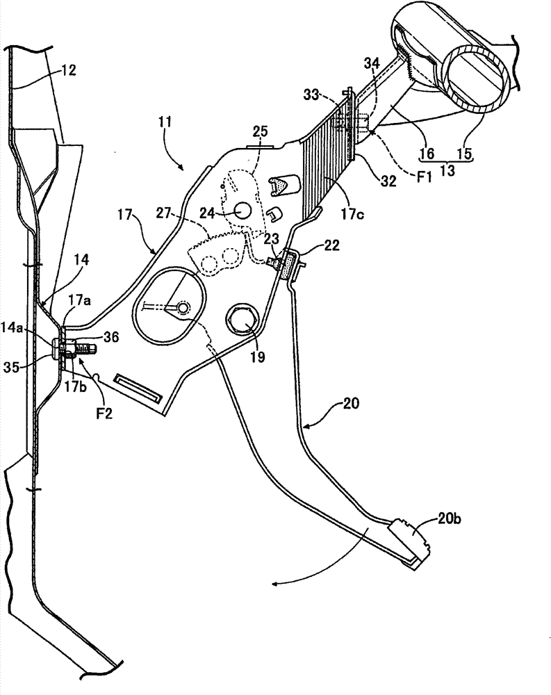
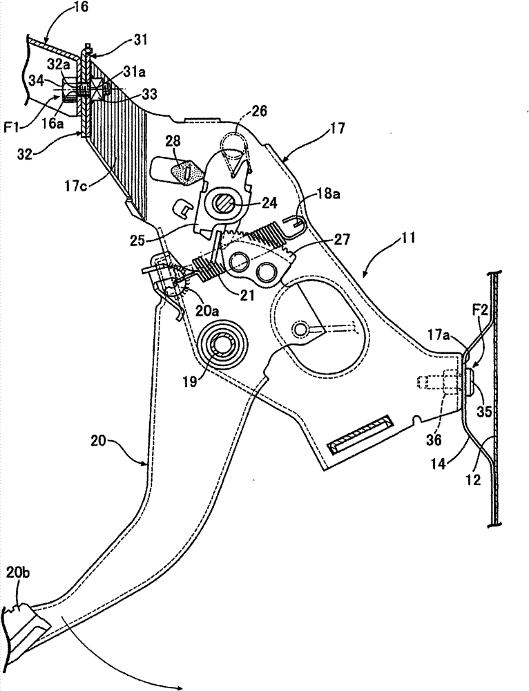
[0037] Figure 1 to Figure 6 represents an embodiment of the present invention, figure 1 is the front view of the parking brake pressure plate unit, figure 2 yes figure 1 The 2-2 line view, image 3 yes figure 1 The 3-3 line view, Figure 4 yes figure 1 The 4-4 line view, Figure 5 yes figure 1 5-5 line to view, Image 6 is corresponding to the figure 1 The function description diagram.

[0038] Such as Figure 1 to Figure 5 As shown, the pedal bracket 11 of the parking brake pedal device operated by the driver is fixed on the instrument panel 12 and the steering hanger 13 in a detachable manner, and the instrument panel 12 separates the engine room and the vehicle compartment. , the steering hanger 13 supports a steering shaft not shown. The rear surface of instrument panel 12 is welded with the panel support 14 that extends on vehicle body left-right direct...


PUM


Abstract

Provided is a fixed structure of a pedal support, even an installing support is removed from a pedal support for supporting a pedal to swing freely, the pedal support is easy to assemble and disassemble relative to an instrument panel or a turning suspension bracket. When the pedal support (11) for supporting the pedal (20) to swing freely is detachably fixed on the instrument panel (12) and the turning suspension bracket (13), a stud (35) fixed on the instrument panel (12) forms a fixed part (F2), a fastening mechanism (14b, 18d) forms another fixed part (F4), therefore, under the state that the pedal support (11) rotates around the stud (35) to unfasten the fastening of the fastening mechanism (14b, 18d), the pedal support (11) can be drawn out from the stud (35), no support is mounted on the pedal support (11), the pedal support (11) can be assembled and disassembled, thus reducting the quantity of the components.

Description

technical field [0001] The present invention relates to a fixing structure of a pedal bracket. The pedal bracket is detachably fixed on a dashboard (dash panel) and a steering hanger (steering hanger) by using a plurality of fixing parts. The pedal bracket supports The driver operates the pedal with his foot and makes the pedal swing freely. Background technique [0002] The fixing structure of such a pedal bracket is known in the following patent document 1. [0003] Such as Figure 7 As shown, the fixing structure of the above-mentioned existing pedal bracket is to fasten the L-shaped mounting bracket 03 on the rear portion of the pedal bracket 02 with bolts 10, and the pedal bracket 02 supports the pedal arm 01 and makes the pedal arm 01 swing freely. The stud bolt (stud bolt) 06 fixes the front part of the pedal bracket 02 to the lower panel 05 of the instrument, screw the nut 07 on the stud bolt 06 and tighten it, and use the bolt 08 to fix the rear part of the pedal b...

Claims


Application Information

Patent Timeline
Patent Type & Authority Patents(China)
IPC IPC(8): B60T7/06
Inventor 铃木泰三小林伸也
Owner HONDA MOTOR CO LTD
Why Eureka
Try Eureka