Mounting fixing mechanism for plough engine

A technology for fixing mechanisms and engines, which is applied to agricultural machinery and implements, and the chassis and applications of agricultural implements. It can solve the problems of easy aging and easy cracking of engine plastic mounting plates, and achieve reduced maintenance costs and good fixation and guidance. , enhance the effect of stability

Inactive Publication Date: 2008-03-19
郭金桃
View PDF0 Cites 0 Cited by
  • Summary
  • Abstract
  • Description
  • Claims
  • Application Information

AI Technical Summary

Problems solved by technology

[0005] In order to effectively solve the problem that the original plastic mounting plate of the engine is easy to break and age, the engine mounting plate is changed to a metal steel plate

Method used


Image

  • Mounting fixing mechanism for plough engine

Examples


Embodiment Construction

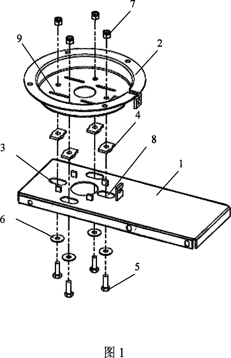
[0011] As shown in the figure, the engine installation and fixing mechanism of the plow machine includes an upper cover plate 1, an engine metal mounting plate 2, a slider 3, a gasket 4, a bolt 5, a flat pad 6 and an insert nut 7; There are four sliding blocks 3 for reducing friction, and the positions of the sliding blocks 3 correspond to the four sliding block grooves 9 on the metal mounting plate 2 of the engine, and the notch length of a single sliding block groove 9 is slightly longer than the length of the sliding block 3 ; Four bolts 5 and four insert nuts 7 correspond to the upper cover plate through holes 8 on the upper cover plate 1 and the screw holes on the engine metal mounting plate 2, and the engine metal mounting plate 2 is connected with the upper cover plate 1; The width of cover plate through hole 8 is equal to the diameter of bolt 5, and the length is 2-3 times of the diameter of bolt 5; The gasket 4 separates the upper cover plate 1 from the metal mounting...


PUM


Abstract

The present invention provides a mounting fixed mechanism for the engine of the plowing machine, which comprises an upper cover plate, an engine metal mounting disc, a sliding block, a gasket, a bolt, an emergency pad and an embedded nut, wherein, the upper cover plate is provided with a sliding block that is used to reduce the friction and the sliding block is correspondent to a sliding-block groove on the engine metal mounting disc; the engine metal mounting disc is fixed with the upper cover plate through the bolt and the embedded nut; the emergency pad is arranged between the bolt and the upper cover plate; the bolt is enclosed with a gasket to separate the upper cover plate and the engine metal mounting disc. The present invention has the advantages that the mounting disc can be firmly fixed without fracture when the machine is vibrating; moreover, the engine mounting disc can be ensured not to be swung for the operation of the motor; thus increasing the stability when the machine is in operation and effectively reducing the repairing charges.

Description

technical field [0001] The invention relates to a fixing device for an engine mounting plate, in particular to a fixing mechanism for a plow engine engine. Background technique [0002] The engine installation and fixing mechanism of the soil plow machine is an indispensable part of the engine installation. The original engine mounting plate of the soil plow machine is made of plastic material, and the mounting plate is directly connected to the upper cover plate, lacking buffer parts. This consideration is mainly Low installation cost once. However, it has been found in practice that the plastic mounting plate is directly connected to the upper cover. The disadvantage is that the plastic mounting plate is easy to break when the machine vibrates, and the clutch thread is easy to slip off. maintenance costs. Contents of the invention [0003] Purpose of the invention: The purpose of the present invention is to address the deficiencies of the prior art and provide a fixing...

Claims


Application Information

Patent Timeline
Patent Type & Authority Applications(China)
IPC IPC(8): A01B51/02
Inventor 郭金桃
Owner 郭金桃
Why Eureka
Try Eureka