Grid structure with lockable edges

A grid and edge locking technology, applied in the field of lockable grid structure, can solve the problems of poor edge locking effect and uneven heating of the grid locking edge.

Pending Publication Date: 2020-03-06
GUANGZHOU ZHUOYUE POWER NEW ENERGY CO LTD
View PDF0 Cites 0 Cited by
  • Summary
  • Abstract
  • Description
  • Claims
  • Application Information

AI Technical Summary

Problems solved by technology

[0004] The present invention intends to provide a grid structure that can be edge-locked to solve the problem in the prior art that the grid is easily unevenly heated during edge-locking, resulting in poor edge-locking effect

Method used


Image

  • Grid structure with lockable edges
  • Grid structure with lockable edges
  • Grid structure with lockable edges

Examples


Embodiment Construction

[0016] The following is further described in detail through specific implementation methods:

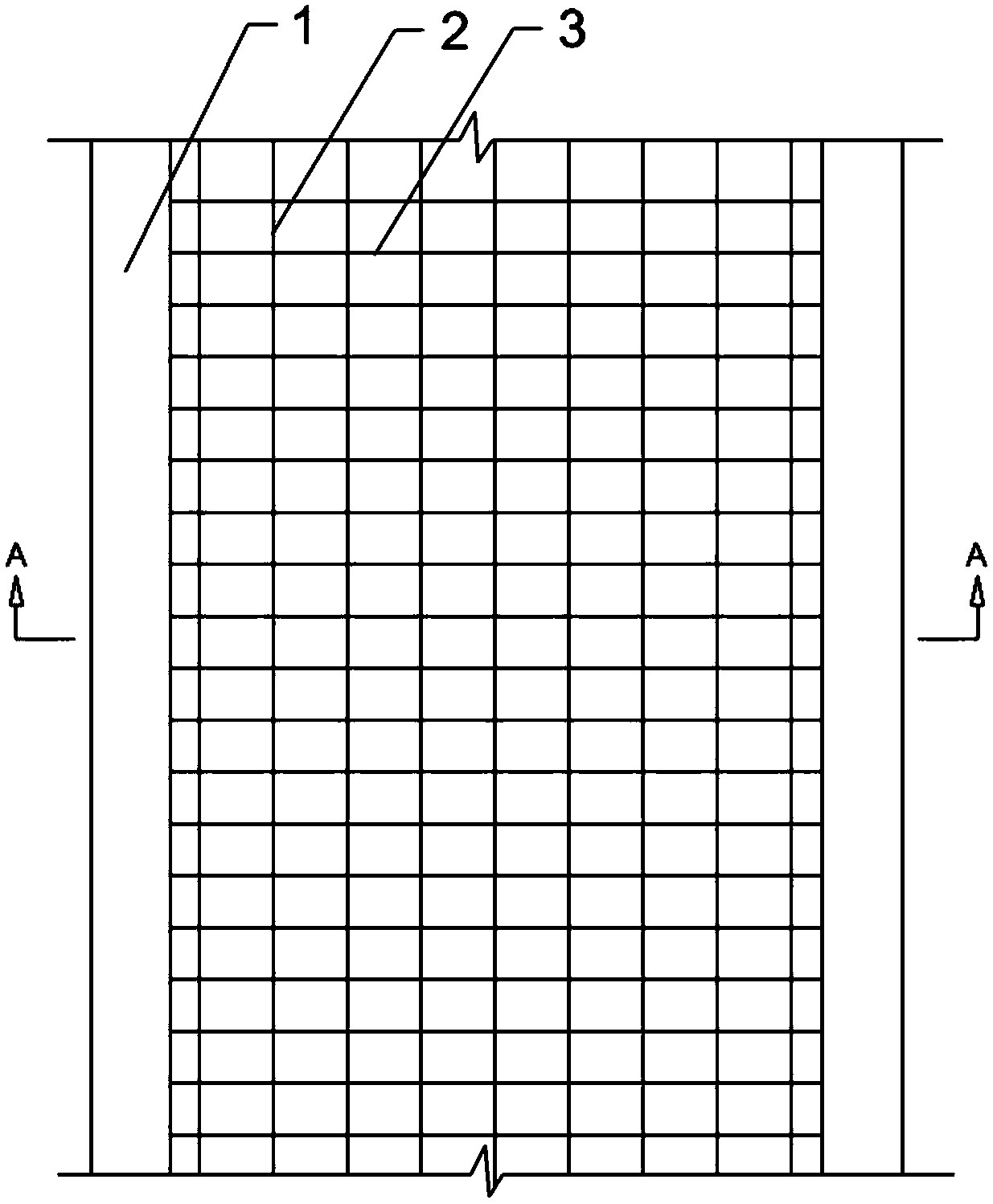
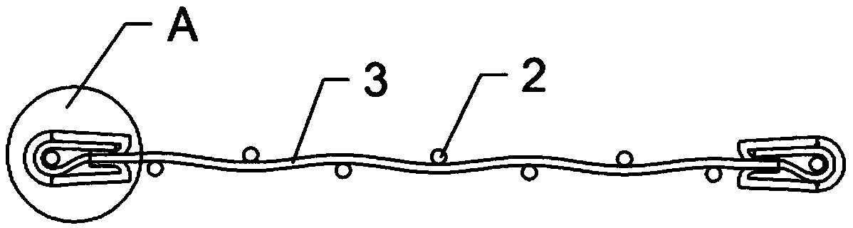
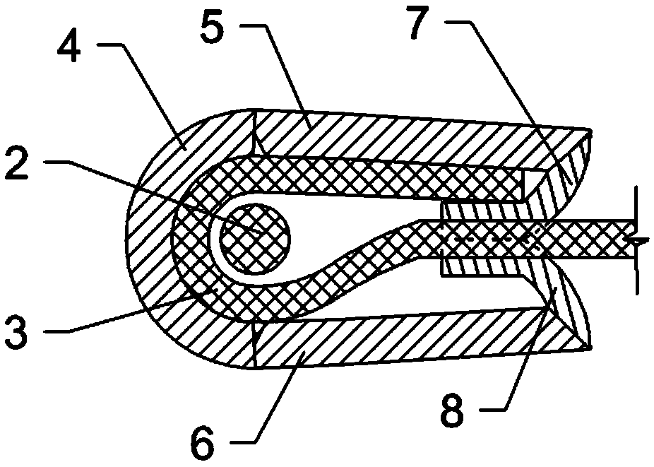
[0017] The reference signs in the accompanying drawings of the specification include: card strip 1, warp thread 2, weft thread 3, vertical plate 4, first side plate 5, second side plate 6, first baffle plate 7, first card slot 71, second The baffle plate 8 and the second card slot 81 .

[0018] The embodiment is basically as attached figure 1 , figure 2 and image 3 Shown: the edge-lockable grid structure, including the grid body, the grid body includes the warp 2 and the weft 3, and the warp 2 and the weft 3 are woven in a cross pattern. The edge of the grid body is provided with clamping strips 1 , and the clamping strips 1 are arranged along a direction parallel to the meridian 2 . The clip 1 includes a first side plate 5, a second side plate 6 and a vertical plate 4, the first side plate 5 and the second side plate 6 are integrally formed with the vertical plate 4, the inter...


PUM


Abstract

The invention relates to the technical field of grid structures of batteries, in particular to a grid structure with lockable edges, which comprises a grid body. The grid body comprises warps and wefts; the warps and the wefts are arranged in a crossed manner; a clamping strip is arranged on the edge of the grid body; the clamping strips are arranged in the direction parallel to the warp; the clamping strip comprises a first side plate, a second side plate and a vertical plate; the vertical plate is located on the outer side of the grid body; the first side plate and the second side plate arelocated on the two sides of the grid body respectively and flexibly connected with the vertical plate; baffles facing the grid body are flexibly connected to the ends, away from the vertical plate, ofthe first side plate and the second side plate; and the end part of the weft at the edge of the grid body bypasses the warp at the edge of the grid body and is propped against the baffle. According to the scheme, the problem that in the prior art, the edge locking effect is poor due to uneven heating during edge locking of the grid is solved.

Description

technical field [0001] The invention relates to the technical field of battery grid structures, in particular to a grid structure capable of locking edges. Background technique [0002] The grid is the main component of the battery, and its functions in the battery are: 1. Support the active material; 2. Make the current evenly distributed on the active material to improve the utilization rate of the active material. The traditional manufacturing methods of the grid include stretching and casting. Among them, the casting is to pour the heated and melted lead alloy into the grid mold under the action of gravity, and then cool and form it, and then process it; the stretching is to pour a certain width The lead strip is made into a prescribed rectangular hole on a punching machine, stretched and shaped. [0003] The grid manufactured by the above method is heavy and has poor corrosion resistance to sulfuric acid, resulting in short service life of the battery and serious envir...

Claims


Application Information

Patent Timeline
Patent Type & Authority Applications(China)
IPC IPC(8): H01M4/73
CPCH01M4/73Y02E60/10
Inventor 何幸华黎少伟李政文何可立马俊
Owner GUANGZHOU ZHUOYUE POWER NEW ENERGY CO LTD
Why Eureka
Try Eureka