Barrel member group and lens capable of intensifying impact bearing

A barrel and lens technology, which is applied in the field of barrel sets and lenses, can solve problems such as reduced output, inability to make thinner products, and uncompetitive products, and achieve the effect of avoiding collapse

Inactive Publication Date: 2008-09-24
ASIA OPTICAL CO INC
View PDF0 Cites 13 Cited by
  • Summary
  • Abstract
  • Description
  • Claims
  • Application Information

AI Technical Summary

Problems solved by technology

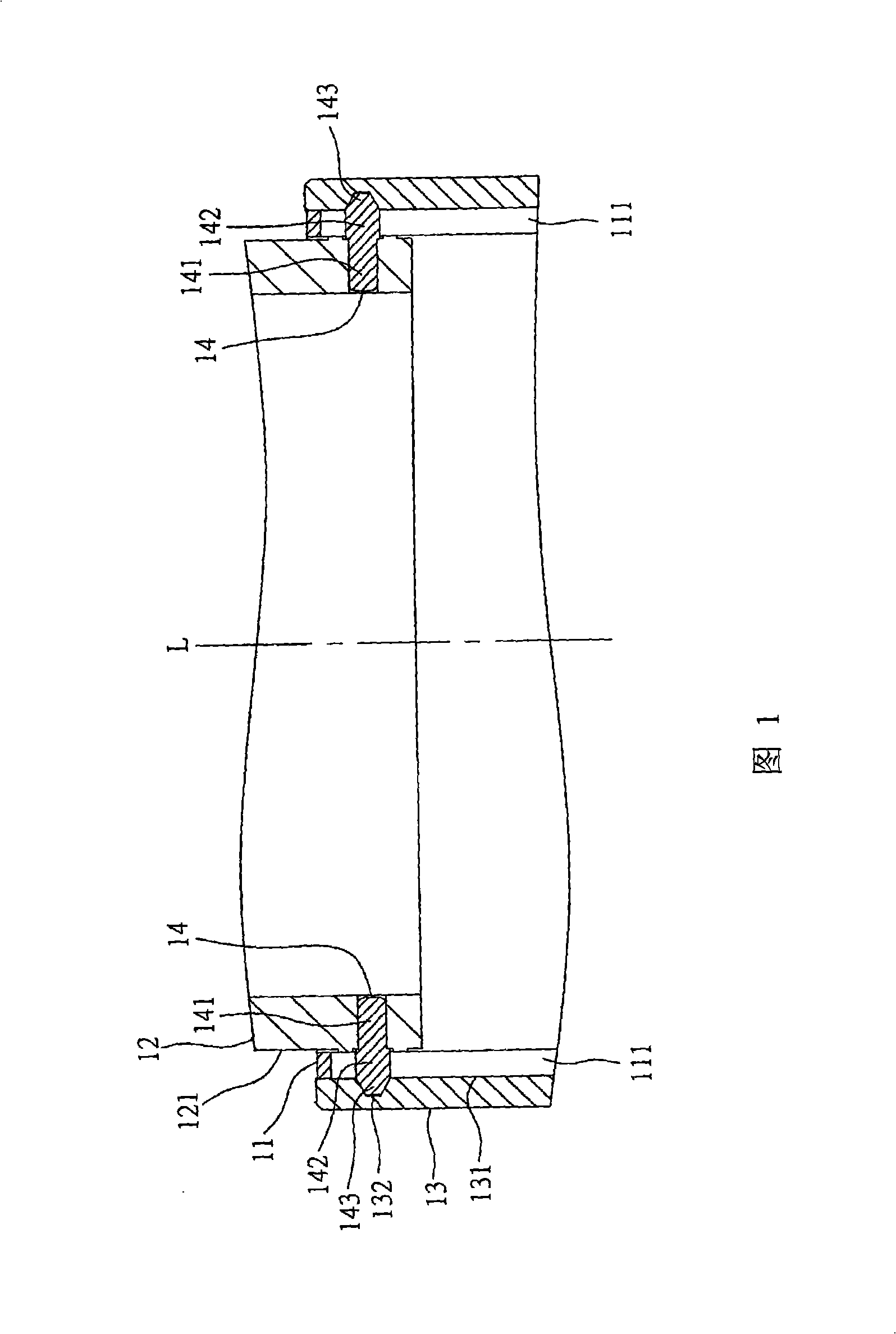
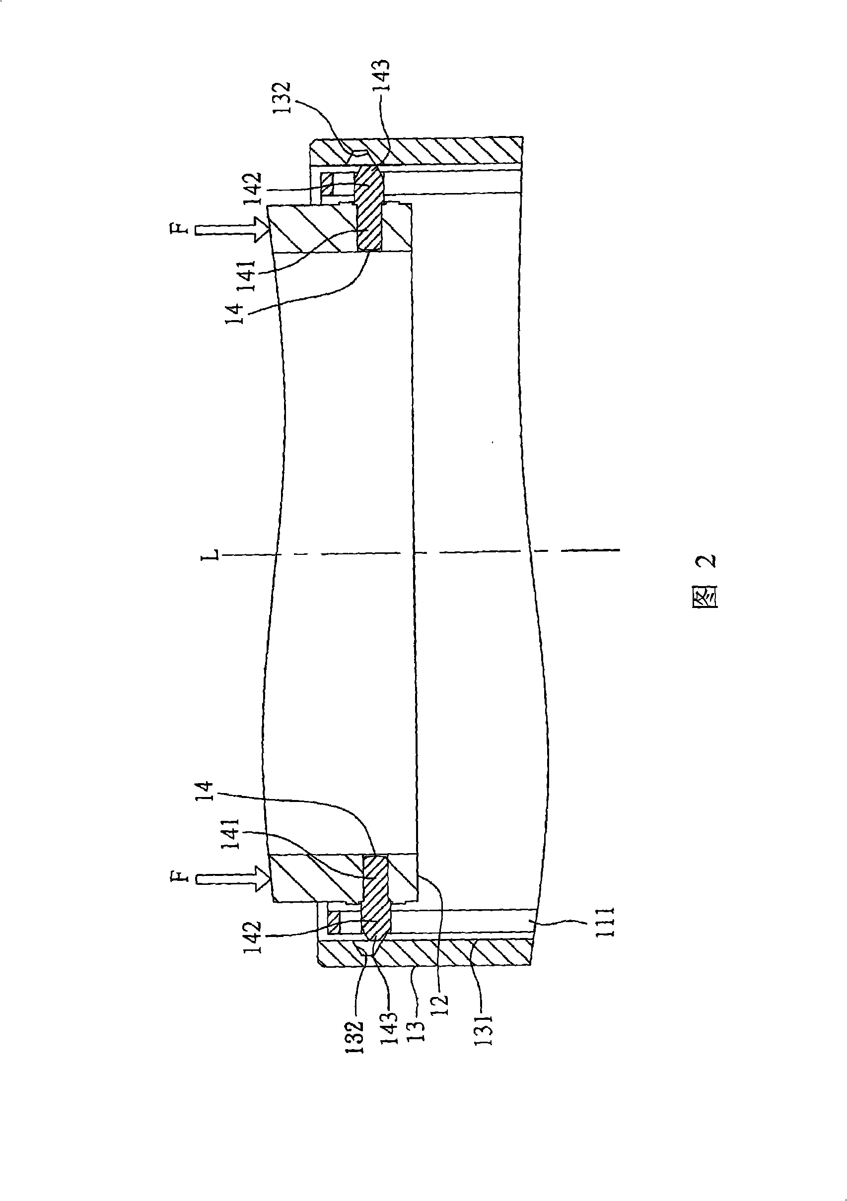
[0005] Although the above-mentioned known lens is retractable, it has the following disadvantages in use: as shown in Figure 2, when the camera is dropped to the ground, if the mirror room unit 12 is impacted by an external force F, it will be connected to the mirror room unit. These interlocking guide pins 14 engagement sections 143 of 12 are simultaneously stressed and easily slip out of these cam grooves 132, the outer lens barrel 13 will be stretched by these interlocking guide pins 14, and the interlocking guide pins 14 connected The mirror chamber unit 12 will also collapse, causing the lens of the camera to jam and malfunction
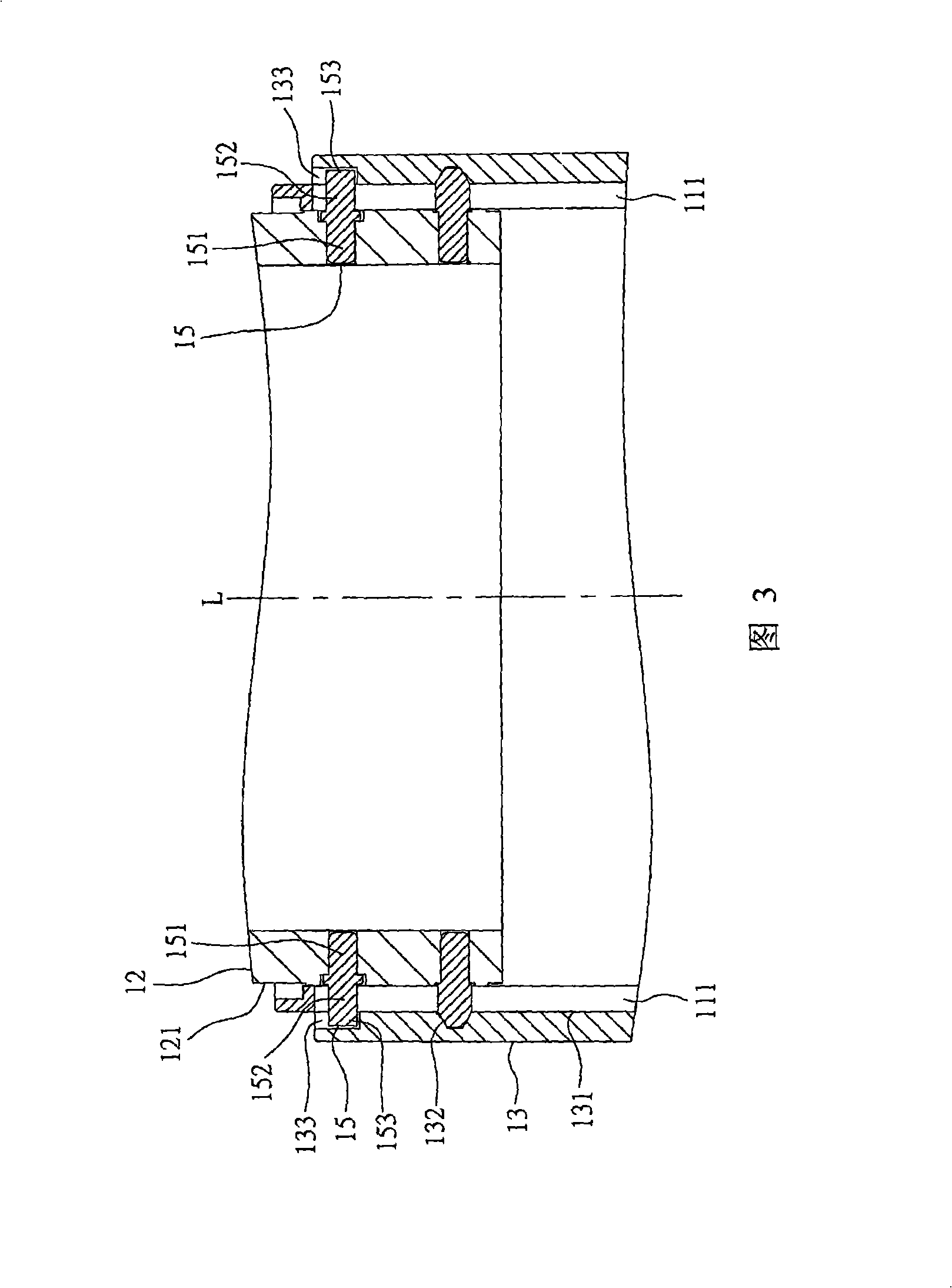
[0008] Although the second known lens can withstand impact, it has the following disadvantages: the outer lens barrel 13 needs to add three additional reinforcements parallel to these cam grooves 132 Groove 133, so that the length of the outer lens barrel 13 and the straight-in barrel 11 increases, the lens becomes thicker and cannot be thinned
And the manufacturer who designs the lens must additionally pay the cost of designing, opening molds and manufacturing these reinforcing pins 15, and assembling these reinforcing pins 15 will also increase the labor cost of assembly and reduce the output, making the product less competitive

Method used


Image

  • Barrel member group and lens capable of intensifying impact bearing
  • Barrel member group and lens capable of intensifying impact bearing
  • Barrel member group and lens capable of intensifying impact bearing

Examples


Embodiment Construction

[0034] The aforementioned and other technical contents, features and effects of the present invention will be clearly presented in the following detailed description of two preferred embodiments with accompanying drawings.

[0035] Before the present invention is described in detail, it should be noted that in the following description, similar components are denoted by the same reference numerals.

[0036] Such as Figure 5 , 6, and 7 are respectively an exploded perspective view of the barrel assembly of the present invention, a side sectional view of the lens of the present invention, and a sectional view of A-A in FIG. 6 . The first preferred embodiment of the impact-resistant barrel assembly of the present invention includes a fixed barrel 20 , a first barrel 30 , a second barrel 40 , three interlocking guide pins 50 , and an outer barrel 60 .

[0037] In a further specific application of the present invention, the fixed cylinder 20 is regarded as a straight-in cylinder, ...


PUM


Abstract

The invention relates to a group of cylinder parts and a lens which can strengthen the impact bearing, the group of the cylinder parts comprise a fixed cylinder, a first cylinder part, a second cylinder part and at least one linking guide pin, the fixed cylinder is provided with a first surface, a second surface and at least one straight advancing ditch, the first cylinder part is mutually sheathed with the fixed cylinder and is provided with a third surface, the second cylinder part is mutually sheathed with the fixed cylinder and is provided with a fourth surface and at least one cam slot, the cam slot is composed of a first slide-connecting surface, a second slide-connecting surface which faces the first slide-connecting surface, a first resistant connecting part and a second resistant connecting part which faces the first resistant connecting part by surrounding and bounding, the linking guide pin is sequentially provided with a joint section, a guide section, the joint section and a strengthening section, and the lens comprises the group of the cylinder parts and is provided with a lens unit which is arranged in the group of the cylinder parts.

Description

technical field [0001] The invention relates to an optical device capable of strengthening impact resistance, in particular to a barrel assembly and a lens capable of strengthening impact resistance. Background technique [0002] As shown in Figure 1, it is a partial cross-sectional view of an existing lens mounted on a camera. A mirror chamber unit 12 , an outer lens barrel 13 set outside the rectilinear barrel 11 , and three interlocking guide pins 14 arranged at intervals. [0003] The straight barrel 11 has three straight grooves 111 arranged at intervals, and each straight groove 111 is arranged parallel to an axis L. As shown in FIG. The outer lens barrel 13 has three cam grooves 132 recessed on an inner wall surface 131 and extending along the circumferential direction at intervals. Each interlocking guide pin 14 is fixed on an outer peripheral surface 121 of the mirror room unit 12, and extends toward the outer lens barrel 13, and has a joint section 141 connected ...

Claims


Application Information

Patent Timeline
Patent Type & Authority Applications(China)
IPC IPC(8): G02B7/02G03B17/04G03B17/02
Inventor 陈宗礼
Owner ASIA OPTICAL CO INC
Why Eureka
Try Eureka