Assistance-free pitch-changing horizontal shaft wind driven generator

A technology for wind turbines and variable pitch, which is applied to wind turbines, wind turbine combinations, and wind turbines that are consistent with the wind direction, etc., and can solve problems such as complex structure, difficulty in manufacturing and installation, and corresponding theoretical rotation angles.

Inactive Publication Date: 2010-04-21
GUANG ZHOU HYENERGY TECH
View PDF2 Cites 13 Cited by
  • Summary
  • Abstract
  • Description
  • Claims
  • Application Information

AI Technical Summary

Problems solved by technology

However, in the field of wind power generators, especially in small and medium-sized wind power generators, the problem of generator damage due to excessive wind speed has always been a difficult technical problem to solve.
This structure is that the wind plate overcomes the elastic force of the compression spring under the action of the wind force to make the push rod rotate the blade through the crank arm. The thrust in the same direction as the thrust of the wind plate, when the wind speed exceeds the maximum wind speed that the wind turbine can withstand, the force acting on the push rod through the wind plate is opposite to the thrust generated by the wind on the blade and hub, so that both There is a phenomenon of offsetting in some directions, so that the actual rotation ang

Method used


Image

  • Assistance-free pitch-changing horizontal shaft wind driven generator
  • Assistance-free pitch-changing horizontal shaft wind driven generator
  • Assistance-free pitch-changing horizontal shaft wind driven generator

Examples


Embodiment Construction

[0013] The present invention will be further described in detail below in conjunction with the accompanying drawings and specific embodiments.

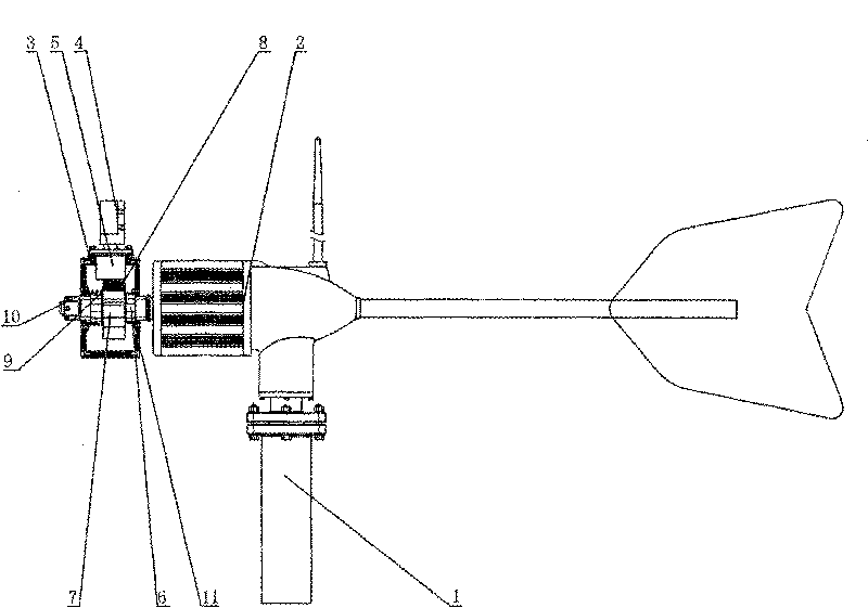
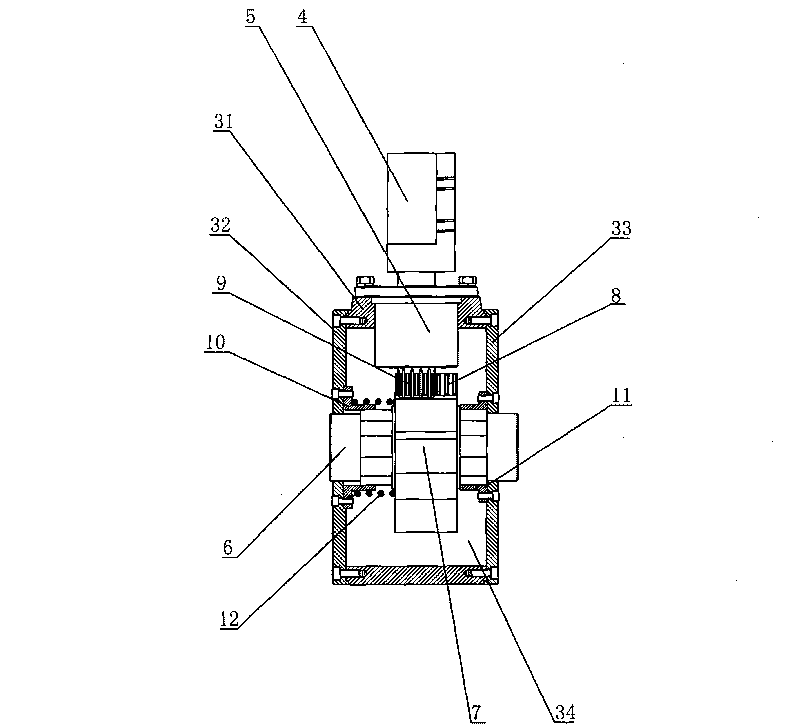
[0014] Such as Figure 1 to Figure 3 The unassisted variable pitch horizontal axis wind turbine includes a tower column 1, a generator set 2, a hub 3, a blade 4, a blade handle 5, a spline shaft 6, a rack seat 7, a rack 8, and a gear 9 , Front spline cover 10, rear spline cover 11, spring 12. The generator set 2 is installed on the tower column 1 . The hub 3 is composed of a hub frame 31, a front end cover 32 and a rear end cover 33, the front end cover 32 is fixed on the front end of the hub frame 31 by screws, and the rear end cover 33 is fixed on the rear end of the hub frame 31 by screws Above, there is a cavity 34 in the hub 3, and three bearing seats are evenly arranged on the hub frame 31, and bearings are arranged on the bearing seats, and the blade handle 5 is installed on the bearing, and one end extends into the cavity 34...


PUM


Abstract

The invention relates to an assistance-free pitch-changing horizontal shaft wind driven generator, which comprises a generator set, a hub, a paddle blade and a paddle blade handle, wherein the hub is provided with more than two bearing blocks; the paddle blade handle is arranged on the bearing blocks through a bearing; the paddle blade is connected with one end part of the paddle blade handle; the hub can move axially on a spline shaft; the spline shaft is provided with a rack block, and the rack block is provided with a rack; one end of the paddle blade handle opposite to the mounted paddle blade is provided with a gear; the gear is meshed with the rack; and a spring is arranged between one lateral surface of the rack block and a cross section of the hub. In the structure, when the actual wind speed is larger than the set wind speed of the wind driven generator, the force acting on the paddle blade and the hub drives the paddle blade and the hub to overcome the elastic force of the spring and move along the axial direction of a spline, the paddle blade handle and the paddle blade are driven to rotate under the action of the rack and the gear, and the pitch angle of the paddle blade is changed, so the wind resistance of the wind driven generator is improved, the pitch-changing accuracy is high, and the structure is simple.

Description

technical field [0001] The invention relates to a variable-pitch wind power generator, in particular to an unassisted pitch-variable structure on a horizontal-axis wind power generator. Background technique [0002] Using natural wind to generate wind power is the full use of renewable energy by human beings. It has the characteristics of convenient and flexible installation, no pollution, and environmental protection, and has attracted more and more attention. However, in the field of wind power generators, especially in small and medium-sized wind power generators, the problem of generator damage due to excessive wind speed has always been a difficult technical problem to solve. In the patent document with the authorized announcement number CN201265487Y and the application date being 2008.5.29, a flying rod synchronous pitch mechanism is disclosed, including a starting spring, a synchronous pull rod, a speed regulating spring, a synchronous guide, a wind hub, a blade flang...

Claims


Application Information

Patent Timeline
IPC IPC(8): F03D9/00F03D1/06F03D7/04H02K7/18F03D9/25F03D15/00
CPCY02E10/723Y02E10/72Y02E10/721
Inventor 赵伟强
Owner GUANG ZHOU HYENERGY TECH
Why Eureka
Try Eureka