A full-distributed heat pipe heat removal cabinet
What is Al technical title?
Al technical title is built by PatSnap Al team. It summarizes the technical point description of the patent document.
A fully distributed, heat pipe technology, used in cooling/ventilation/heating renovation, instruments, electrical and digital data processing, etc., can solve the problem of water cooling cabinet door water entering the machine room, etc., to ensure safety, improve safety, and efficiently remove heat. Effect
Active Publication Date: 2016-03-02
BEIJING NYF SCI & TECH DEV CO LTD
View PDF3 Cites 0 Cited by
Summary
Abstract
Description
Claims
Application Information
AI Technical Summary
This helps you quickly interpret patents by identifying the three key elements:
Problems solved by technology
Method used
Benefits of technology
Problems solved by technology
[0006] The third is to use the water-cooled cabinet door to replace the heat dissipation method of the front and rear door panels of the cabinet in the computer room. This method achieves the effect of being close to the heat source of the server and cooling nearby, but the water-cooled cabinet door has the hidden danger of water entering the computer room
Method used
Image
Click on the blue label to locate the original text in one second.
Reading with bidirectional positioning of images and text.
Examples
Embodiment Construction
[0020] In order to make the object, technical solution and advantages of the present invention clearer, the present invention will be further described in detail below with reference to the accompanying drawings and examples.
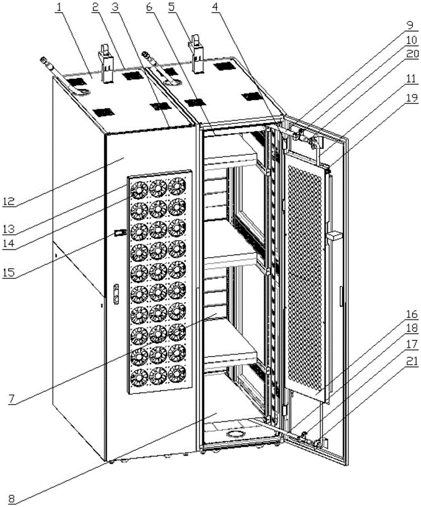
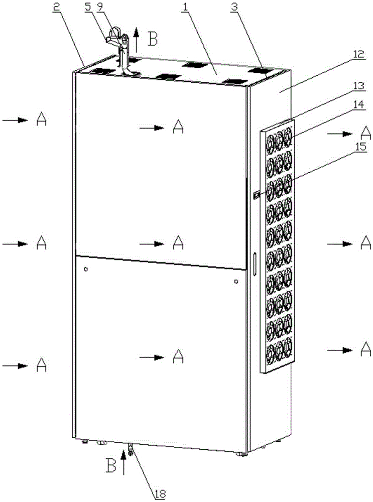
[0021] figure 1 It is a structural schematic diagram of the full-distributed heat exhaust cabinet of the present invention. The full cloth heat exhaust cabinet of the present invention includes a movable bracket 1 with side panels, a mesh front door 2, a back panel 3, a reinforced hinge 4, a height-adjustable header bracket 5, a trachea hose partition 6, and a sealing assembly 7. Liquid pipe hose partition 8. Among them, the back panel 3 is composed of a trachea hose 9, a trachea fixing assembly 10, a heat pipe heat exchanger 11, a back panel frame sheet metal 12, a fan mounting plate 13, a small axial flow fan 14, a controller 15, and a mesh cover plate 16. The liquid pipe fixing assembly 17 is composed of a liquid pipe hose 18; the heat pipe heat ex...
PUM
Abstract
The invention provides a full-covered type heat pipe heat removal cabinet which is used for carrying out heat removal on high radiating density rack servers inside a machine room. The full-covered type heat pipe heat removal cabinet is composed of a movable support with side plates, a mesh front door, a rear back plate, reinforcing hinges, a height adjustable header support, an air hose separating plate, a sealing assembly and a liquid hose separating plate, wherein the rear back plate is composed of an air hose, an air pipe fixing assembly, a heat pipe exchanger, a rear back plate frame metal sheet, a fan mounting plate, small axial flow fans, a controller, a mesh cover plate, a liquid pipe fixing assembly and a liquid pipe hose, and the heat pipe exchanger is composed of a heat exchange core body, an air pipe connector and a liquid pipe connector. According to the full-covered type heat pipe heat removal cabinet, the demands for control over the temperature of the high radiating density rack servers in the machine room is combined, the distribution of full-covered type small axial flow fans is adopted, efficient heat removal is achieved by improving heat removal evenness, and the thickness space of the rear back plate can be saved; the mode that the hoses are arranged inside the rack is adopted, the effect that the hoses swing freely along with the opening and the closing of the rear back plate is achieved, the service life of the hoses is prolonged, and the safety of the system is improved; through the design and selection of the structure and accessories, the full-covered type heat pipe heat removal cabinet is suitable for various construction conditions and ensures safe and reliable operation of products.
Description
technical field [0001] The invention relates to the field of heat exhaustion in a computer room with high heat dissipation density, relates to a server heat exhaustion cabinet, in particular to a full-distributed heat pipe heat exhaustion cabinet. Background technique [0002] The integration density of cabinet servers in the computer room is getting higher and higher, and the heat generated by the server is getting larger and larger. In order to ensure that the servers in the high heat dissipation density computer room work at the most suitable ambient temperature, the current heat dissipation method of the high heat dissipation density computer room is also constantly changing. . [0003] At present, there are three main ways to dissipate heat in a computer room with high heat dissipation density: [0004] One is precise air supply from the precision air conditioner. In this way, air ducts are used in the machine room to direct the cold air from the precision air conditio...
Claims
Application Information
Patent Timeline
Application Date:The date an application was filed.
Publication Date:The date a patent or application was officially published.
First Publication Date:The earliest publication date of a patent with the same application number.
Issue Date:Publication date of the patent grant document.
PCT Entry Date:The Entry date of PCT National Phase.
Estimated Expiry Date:The statutory expiry date of a patent right according to the Patent Law, and it is the longest term of protection that the patent right can achieve without the termination of the patent right due to other reasons(Term extension factor has been taken into account ).
Invalid Date:Actual expiry date is based on effective date or publication date of legal transaction data of invalid patent.