Ammonia-cooled ammonia reclamation method and mating device thereof

A kind of ammonia recovery and self-cooling technology, applied in the direction of ammonia preparation/separation, etc., can solve the problems of high impurity content in the inlet gas, large construction investment, high steam consumption, etc., to improve the utilization rate of raw materials, solve the expansion of ammonia water, reduce the The effect of energy consumption

Inactive Publication Date: 2011-01-26
甘肃金昌化学工业集团有限公司
View PDF0 Cites 11 Cited by
  • Summary
  • Abstract
  • Description
  • Claims
  • Application Information

AI Technical Summary

Problems solved by technology

[0002] In the production process of synthetic ammonia, the ammonia content in the vent gas of the liquid ammonia storage tank reaches more than 50%, which needs to be recovered through the ammonia recovery process. Power ammonia recovery process, etc., but the above process technologies have the disadvantages of excessive ammonia water, high steam consumption, large construction investment, and high requirements for impurity content in the inlet gas, which need to be further improved

Method used


Image

  • Ammonia-cooled ammonia reclamation method and mating device thereof
  • Ammonia-cooled ammonia reclamation method and mating device thereof

Examples


Embodiment 1

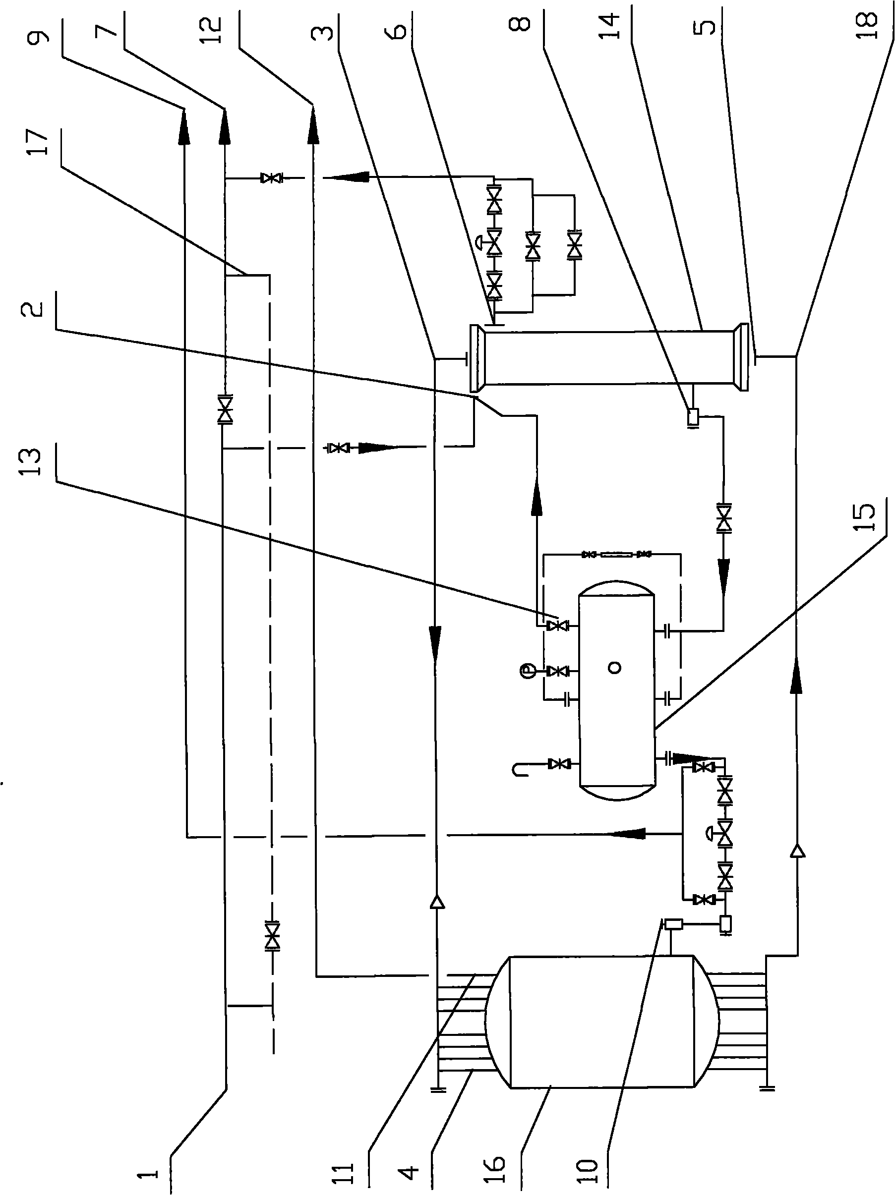
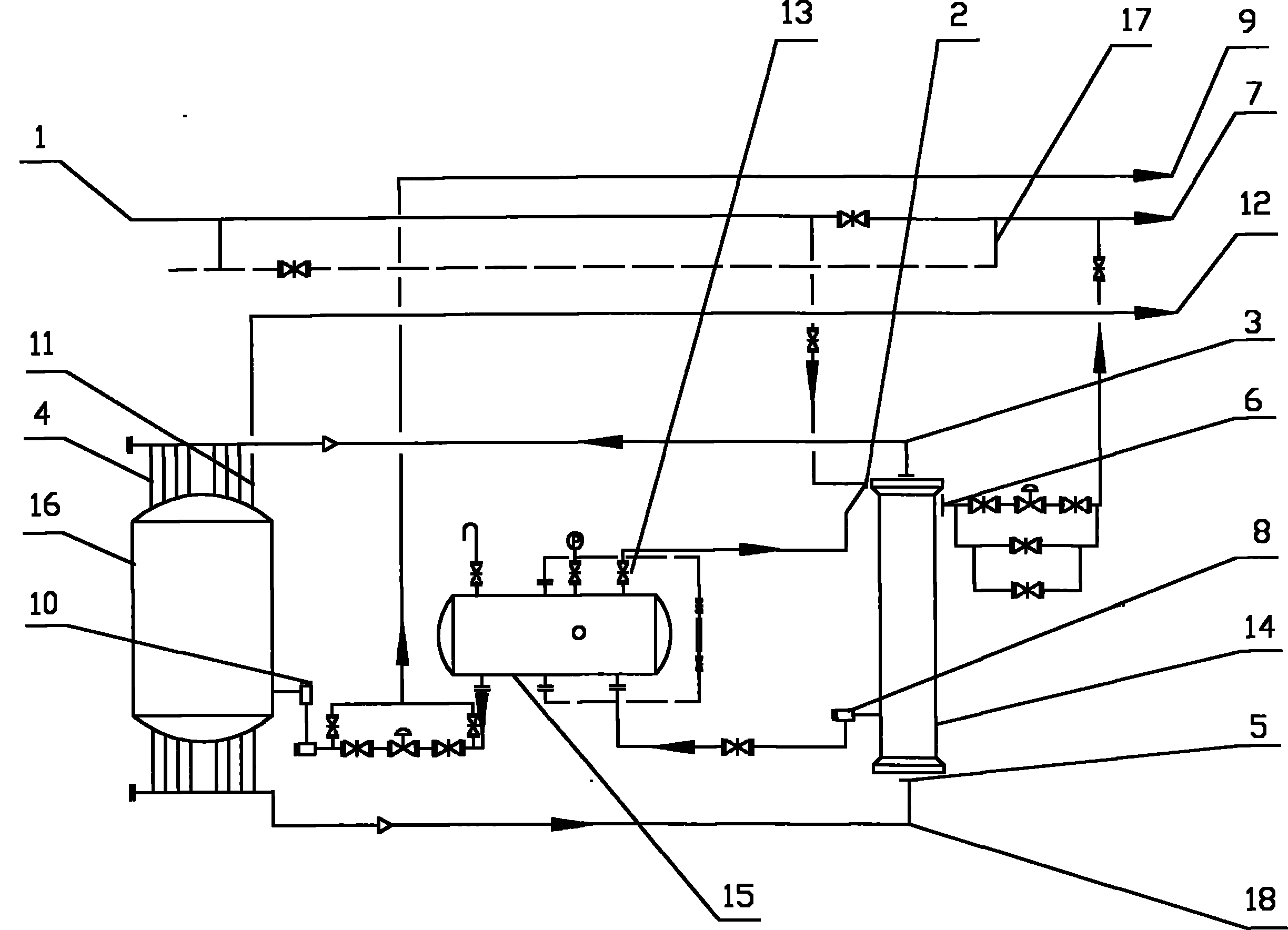
[0018] 1. The relaxation gas from the liquid ammonia storage tank, containing 45% ammonia, enters the cold heat exchanger tube at a temperature of 15 °C, exchanges heat with the cold relaxation gas between the tubes, and comes out of the cold heat exchanger tube after cooling down to 5 °C. Then enter the ammonia evaporation condenser tube, in the ammonia evaporation condenser, the gaseous ammonia is greatly cooled to -10°C and condensed into liquid ammonia;

[0019] 2. After the ammonia is condensed, the release gas entrains the liquid ammonia mist and comes out from the bottom of the ammonia evaporator condenser, and then enters between the cold and heat exchanger tubes again. The release gas undergoes gas-liquid separation between the cold and heat exchanger tubes and absorbs the heat of the gas in the tubes , the liquid ammonia is separated and accumulated at the bottom of the cold heat exchanger; the temperature of the released gas after separation of ammonia is raised to 5...

Embodiment 2

[0024] 1. The release gas from the liquid ammonia storage tank, containing 42% ammonia, enters the cold heat exchanger tube at a temperature of 15°C, exchanges heat with the cold release gas between the tubes, and comes out of the cold heat exchanger tube after cooling down to 5°C. Then enter the ammonia evaporation condenser tube, in the ammonia evaporation condenser, the gaseous ammonia is greatly cooled to -10°C and condensed into liquid ammonia;

[0025] 2. After the ammonia is condensed, the release gas entrains the liquid ammonia mist and comes out from the bottom of the ammonia evaporator condenser, and then enters between the cold and heat exchanger tubes again. The release gas undergoes gas-liquid separation between the cold and heat exchanger tubes and absorbs the heat of the gas in the tubes , the liquid ammonia is separated and accumulated at the bottom of the cold heat exchanger; the temperature of the released gas after separation of ammonia is raised to 5°C, and ...

Embodiment 3

[0030] 1. The release gas from the liquid ammonia storage tank, containing 48% ammonia, enters the cold heat exchanger tube at a temperature of 15°C, exchanges heat with the cold release gas between the tubes, and comes out of the cold heat exchanger tube after cooling down to 5°C. Then enter the ammonia evaporation condenser tube, in the ammonia evaporation condenser, the gaseous ammonia is greatly cooled to -10°C and condensed into liquid ammonia;

[0031] 2. After the ammonia is condensed, the release gas entrains the liquid ammonia mist and comes out from the bottom of the ammonia evaporator condenser, and then enters between the cold and heat exchanger tubes again. The release gas undergoes gas-liquid separation between the cold and heat exchanger tubes and absorbs the heat of the gas in the tube , the liquid ammonia is separated and accumulated at the bottom of the cold heat exchanger; the temperature of the released gas after separation of ammonia is raised to 5°C, and i...


PUM


Abstract

The invention discloses an ammonia-cooled ammonia reclamation method and a mating device thereof. Gas phase ammonia in purge gas is condensed into liquid ammonia by using the principle of ammonia decompressed evaporation and refrigeration, and the separated liquid ammonia is used as a refrigerant for continuously cooling the gas phase ammonia in the purge gas, over and over again. The eliminated high-pressure equipment and pipelines which still can be continuously used in the ammonia synthesis process are used for decompression to form an ammonia-cooled ammonia reclamation device, wherein the device comprises a purge gas pipeline, a cold and heat exchanger, an ammonia evaporation condenser and a liquid ammonia storage tank; and the formed ammonia-cooled separation circulating process in the purge gas is characterized in that: the liquid ammonia prepared from the purge gas is conveyed into the ammonia evaporation condenser and evaporated into gaseous ammonia so as to obtain a large amount of cold energy, and the gaseous ammonia in the purge gas is continuously cooled so as to fulfill the purpose of separating the gas phase ammonia in the purge gas. The device has the advantages of energy conservation, low investment and good usability.

Description

technical field [0001] The invention relates to the field of synthetic ammonia production, in particular to an ammonia self-cooling ammonia recovery method for recovering the ammonia content in purge gas, and the invention also includes a supporting device for the method. Background technique [0002] During the production process of synthetic ammonia, the ammonia content in the vent gas of the liquid ammonia storage tank reaches more than 50%, which needs to be recovered through the ammonia recovery process. Power ammonia recovery process, etc., but the above process technologies have the disadvantages of excessive ammonia water, high steam consumption, large construction investment, and high requirements for impurity content in the inlet gas, which need to be further improved. Contents of the invention [0003] The technical problem to be solved by the present invention is to provide an ammonia self-cooling ammonia recovery method and its supporting device, which can mak...

Claims


Application Information

Patent Timeline
Patent Type & Authority Applications(China)
IPC IPC(8): C01C1/12
Inventor 王明陈嘉彪于伟李梅杨敏
Owner 甘肃金昌化学工业集团有限公司
Why Eureka
Try Eureka