Tool for bending process of bending press

A press brake and tool technology, applied in the field of press bending tools, can solve the problems of position deviation, inability to perform bending process, scratches, etc.

Active Publication Date: 2011-03-30
牧野 攻
View PDF7 Cites 1 Cited by
  • Summary
  • Abstract
  • Description
  • Claims
  • Application Information

AI Technical Summary

Problems solved by technology

Affected by this setting, when the workpiece is long (compared to the processing material of the general standard length), especially the part of the workpiece that is closest to the lower end of the machine, sometimes the bending process cannot be performed when it is to be bent.
Usually, the bending processing machine is used for processing, and the processed product used for processing is often long in length. In this case, the processed product (beside the lower end) and the processing machine (part) should be If you can't touch it, if you can't remove the obstacle, it will cause the problem that you can't process it, resulting in a decrease in workability.
[0012] [2] The above-mentioned bending tool is divided into two equal parts of the knife tip, which is squeezed into each V from the contact part of the workpiece to the gap next to the blade side of the lower V-shaped bending die. Type bending die, in order to achieve the effect of bending into a right angle, so the processed product has a relatively rapid phenomenon in the bending process, so the processed product is prone to scratches after processing
Moreover, during the bending process, during the bending process, especially at the lower end surface of the workpiece, it will drop sharply from the horizontal direction to the direction of 45°, and there will be safety concerns in the processing.
[0013] [3] Due to the above-mentioned bending tools, the relative movement of the upper V-shaped bending die and the lower V-shaped bending die presses the workpiece at a position where the cutting edge of each V-shaped bending die is deviated. Therefore, when the pressure is applied, the position of each V-shaped bending die is prone to deviation, especially the lower V-shaped bending die, because it is generally only locked on the table with screws, it is prone to position deviation.
Moreover, because the V-shaped bending mold is easy to deviate, it is very difficult to extend the length of the mold, or to connect other molds in order to extend it, and the bending length of the bending tool cannot be increased.

Method used


Image

  • Tool for bending process of bending press
  • Tool for bending process of bending press
  • Tool for bending process of bending press

Examples


Embodiment Construction

[0034] In order to present the content of the present invention more specifically, the implementation forms of the present invention will be described in detail below with reference to the drawings.

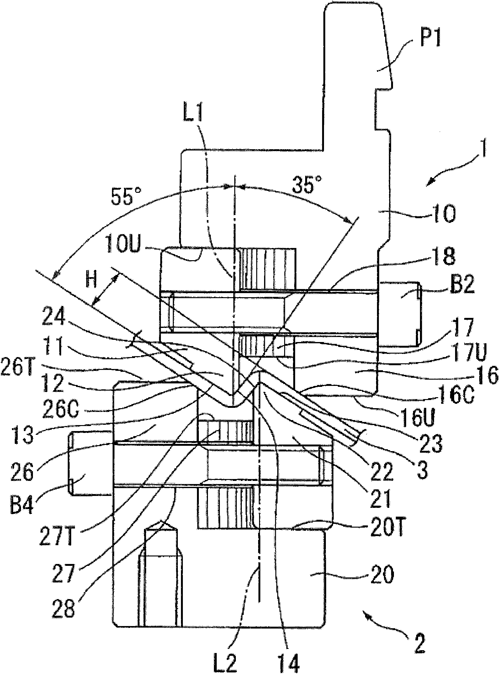
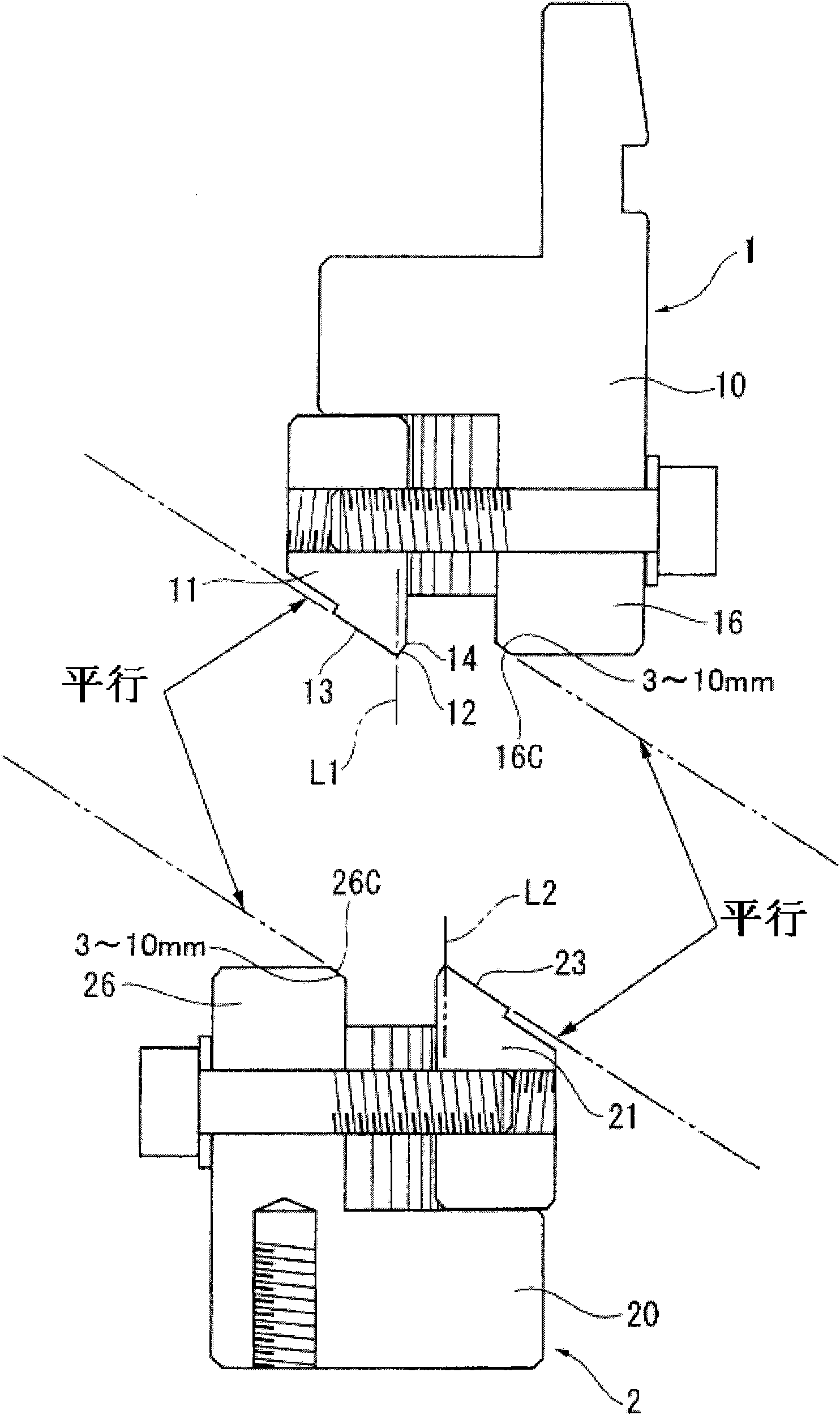
[0035] Such as figure 1 As shown, this bending tool is composed of an upper V-shaped bending die 1 and a lower V-shaped bending die 2.

[0036] The fixing part P1 at the upper end of the upper V-shaped bending die 1 is fixed to the main body of the bending machine with a nut or other suitable locking fittings. This upper V-shaped bending die 1, the V-shaped bending die body 10, is provided with a downwardly protruding blade 11 and a bending processing block 16 (hereinafter Referred to as processing block 16).

[0037] In the structure of the above-mentioned upper V-shaped bending die 1, the V-shaped bending die body 10 and the processing blocks 16 are integrally formed, and the blade 11 is formed after the V-shaped bending die body 10 and each processing block 16 are formed. T...


PUM


Abstract

The invention aims to provide a tool for bending process of a bending press to enlarge the length of a to-be-bent object without causing scratches. Technically, an angle formed between knifepoint split lines L 1 and L2 of blades in V-shaped bend moulds and an outside rhombus side of a cross section of the V-shaped bend mould is set to be larger than an angle between the knifepoint split lines L1 and L2 and an inside diamond of the cross section, and an angle between an internal edge of a processing block of the V-shaped bend mould on one side and the outside rhombus side of the cross section of the V-shaped bend mould on the other side is parallel to a chamfering part, the chamfering parts 16 C and 26C forming the internal edges of the rhombus side are shorter, the V-shaped bend mould is positioned in a center position among the knifepoint split line L1 of the V-shaped bend mould on one side, the knifepoint split line L2 of the V-shaped bend mould on the other side and the internal edges of the processing block, i.e. a position closer than the knifepoint split line L2 of the V-shaped bend mould on the other side.

Description

technical field [0001] The invention relates to a tool for bending processing of a bending machine, which is installed on a bending machine (also known as a bending plate brake) and can be used for stamping and bending processing of machine products such as metal plates. Bending tools (hereinafter referred to as bending tools). Background technique [0002] The structure of this kind of bending tool is also found in Patent Document 1 (Japanese Patent Publication No. 1707773), and what is shown in Patent Document 1 is the applicant's previous patent application. The bending tool described in this patent document 1 is formed by two V-shaped bending dies. On each V-shaped bending die, a V-shaped bending die body is respectively arranged. The head, the dividing line (central line) of the cutting edge extending in the vertical direction, is divided into two equal parts, forming a cutting edge with a slightly 90° cutting edge, the cutting edge is equipped with an adjustable inter...

Claims


Application Information

Patent Timeline
Patent Type & Authority Applications(China)
IPC IPC(8): B21D5/06
Inventor 牧野攻
Owner 牧野 攻
Why Eureka
Try Eureka