Conveying method for bottom discharge bin pump

A silo pump and ash conveying pipeline technology, which is applied in the field of downdraft silo pump pneumatic conveying, can solve the problems of difficulty in reasonable configuration, clogging of ash conveying pipeline, easy clogging, etc., so as to improve conveying efficiency, reduce unit gas consumption and unit energy consumption Effect

Inactive Publication Date: 2011-04-13
ZHENJIANG CITY POWER STATION AUXILIARY MACHINERY PLANT
View PDF0 Cites 8 Cited by
  • Summary
  • Abstract
  • Description
  • Claims
  • Application Information

AI Technical Summary

Problems solved by technology

[0004] 1. The existing down-drawing silo pump usually adopts silicon carbide porous plate. Since the silicon carbide porous plate is easy to block, the dry ash in the silo pump cannot be fully fluidized, which reduces the flow performance of the dry ash. The dry ash in the silo pump Easy to bridge, affecting the ash output of the warehouse pump
[0005] 2. When the pressure in the warehouse pump is less than or equal to the pressure in the ash conveying pipeline, the ash in the warehouse pump will not be ash due to the support of the conveying compressed air. When the pressure in the warehouse pump is greater than the pressure in the ash conveying pipe, the dry ash in the warehouse pump will be The speed is pressed into the ash conveying pipeline, so that the conveying compressed air cannot convey dry ash, causing the ash conveying pipeline to be blocked
[0006] 3. Uncertain factors such as the volume of the down-drawing warehouse pump and the diameter of the ash conveying pipeline are difficult to be reasonably configured and the length of the horizontal ash conveying pipeline at the outlet of the down-drawing warehouse pump is limited, which reduces the reliability of the down-drawing warehouse pump.

Method used


Image

  • Conveying method for bottom discharge bin pump
  • Conveying method for bottom discharge bin pump

Examples


Embodiment Construction

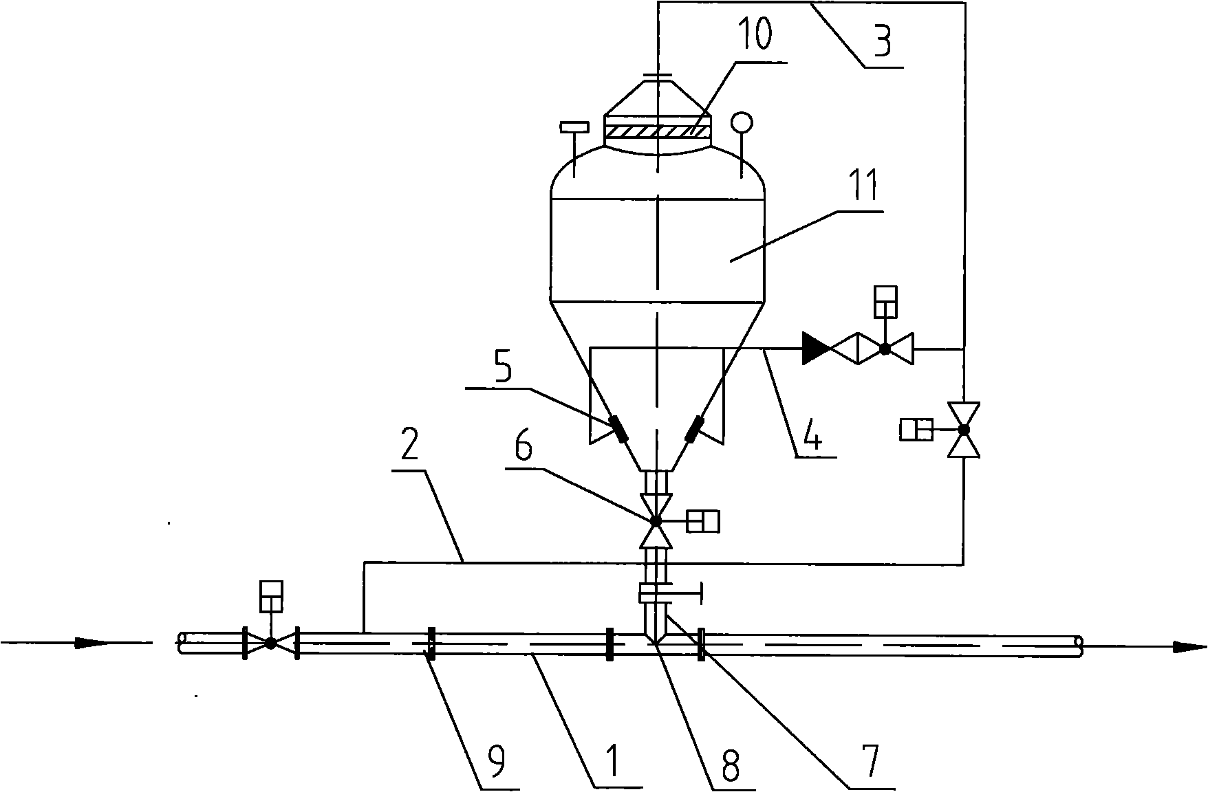
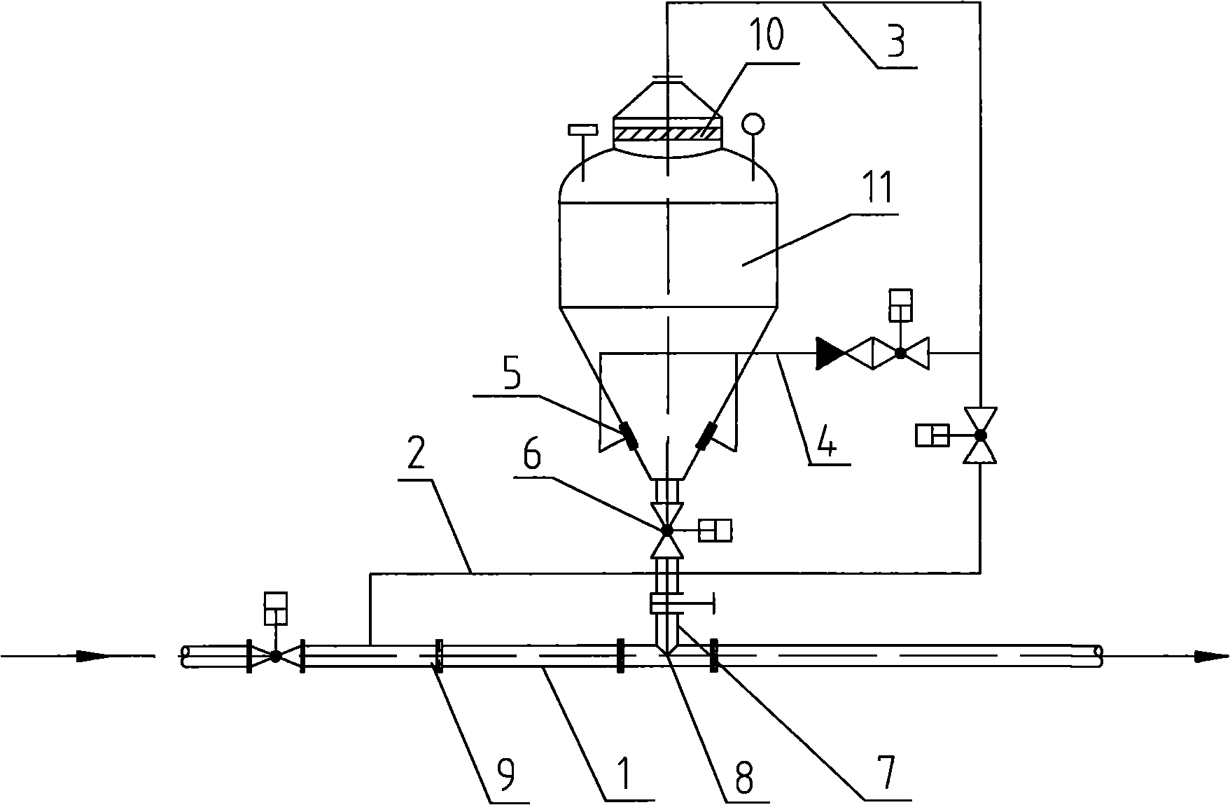
[0019] Below in conjunction with the accompanying drawings, the delivery method of the down-drawing type warehouse pump provided by the invention will be further described in detail:

[0020] The compressed air enters the pressurized fluidization pipeline 2, and pressurizes the warehouse pump 11 through the pressurized pipeline 3; the compressed air enters the fluidization device 5 in the warehouse pump through the fluidization pipeline 4, and performs fluidization treatment on the dry ash in the warehouse pump 11 ; When the pressure in the warehouse pump reaches the preset value, the pneumatic discharge valve 6 is opened, and the dry ash enters the positive pressure ash conveying pipeline 1 through the ash conveying pipeline inlet 8, and the flow regulating device on the positive pressure ash conveying pipeline 1 is adjusted 9. Control the ash output speed of dry ash until the dry ash is conveyed.

[0021] The fluidization device in the warehouse pump is a butterfly gasificat...


PUM


Abstract

The invention discloses a conveying method for a bottom discharge bin pump, which comprises the following steps of: 1, enabling a compressed air to enter a pressurized and fluidized pipeline, and pressurizing a bin pump through the pressurized pipe; 2, enabling the compressed air to enter a fluidizing device in the bin pump through the fluidized pipeline for fluidizing dry ash in the bin pump; and 3, when the pressure in the bin pump reaches the preset value, opening a pneumatic discharge valve, enabling the dry ash to enter a positive pressure ash conveying pipeline through a feeding hole of an ash conveying pipeline, regulating a flow regulating device on the positive pressure ash conveying pipeline, and controlling the discharge speed of the dry ash until the dry ash is conveyed completely, thereby improving the ash discharge and conveying reliability of the bottom discharge bin pump, increasing the conveying efficiency, and lowering the conveying unit gas consumption and the unit energy consumption.

Description

technical field [0001] The invention relates to a down-drawing warehouse pump pneumatic conveying method, in particular to a down-drawing warehouse pump conveying method in a pneumatic ash removal system device of a large and medium-sized coal-fired power plant, and a limestone powder pneumatic conveying system of a boiler flue gas desulfurization system. Background technique [0002] In the pneumatic conveying project, the conveying equipment with two discharge methods, the upward-drawing warehouse pump or the downward-drawing warehouse pump, is usually used. Due to the difficulty of controlling the discharge speed of the existing down-drawing silo pumps and easy pipe blockage, it is rarely used in medium and long-distance pneumatic ash removal projects. [0003] The down-drawing type silo pump relies on the joint action of the pressure inside the silo pump, the pressure difference in the conveying pipeline and the dry ash self-weight to press the dry ash in the silo pump i...

Claims


Application Information

Patent Timeline
Patent Type & Authority Applications(China)
IPC IPC(8): B65G53/16B65G53/58
Inventor 虞瑞鹤崔功龙张凯
Owner ZHENJIANG CITY POWER STATION AUXILIARY MACHINERY PLANT
Why Eureka
Try Eureka