Stereo projecting equipment

A stereoscopic projection and equipment technology, applied in stereophotography, photography, optics, etc., can solve problems affecting the overall projection effect of stereoscopic projection equipment

Inactive Publication Date: 2011-06-08
SHENZHEN GRADUATE SCHOOL TSINGHUA UNIV
View PDF6 Cites 20 Cited by
  • Summary
  • Abstract
  • Description
  • Claims
  • Application Information

AI Technical Summary

Problems solved by technology

If the spatial arrangement of the two channels is asymmetrical, it will serious

Method used


Image

  • Stereo projecting equipment
  • Stereo projecting equipment
  • Stereo projecting equipment

Examples


Embodiment Construction

[0027] Below in conjunction with accompanying drawing, preferred embodiment of the present invention is described in further detail:

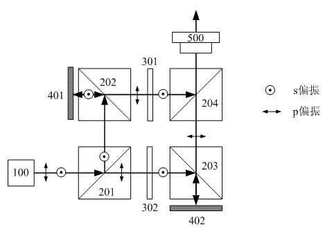
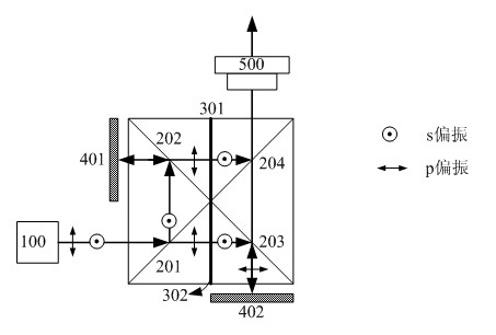
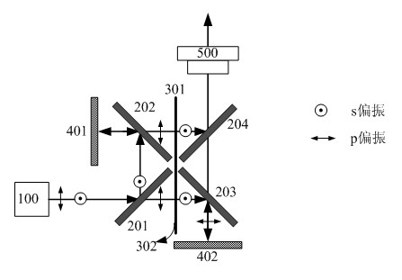
[0028] Such as figure 1 As shown, a stereoscopic projection device includes: a light source assembly 100; four polarizing beam-splitting prisms 201, 202, 203 and 204; two white light wave plates 301 and 302; two LCOS panels 401 and 402.

[0029] Wherein, the light source assembly 100 is used to emit a shaped and uniform natural light or an illumination beam of circularly polarized light. In order to realize color display, the illuminating light beam may be a white light beam, or sequential monochromatic light.

[0030] The polarization beam splitter 201 is used to split the natural light or the circularly polarized illumination beam into s-polarized light and p-polarized light whose polarization states are perpendicular to each other.

[0031] The s-polarized light beam enters the polarization beam splitter 202, is reflected and irradiates on...


PUM


Abstract

The invention provides stereo projecting equipment which comprises a light source assembly, a first polarizing beam splitter, a second polarizing beam splitter, a third polarizing beam splitter, a fourth polarizing beam splitter, a first polarizing converter, a second polarizing converter, a first reflection type electrooptical modulator, a second reflection type electrooptical modulator and a projecting lens, wherein light emitted by the light source assembly is split into a first polarizing light beam and a second polarizing light beam by the first polarizing beam splitter, and the polarizing states of the two polarizing light beams are mutually vertical; the first polarizing light beam is reflected to the second polarizing light beam splitter by the first polarizing beam splitter; and the second polarizing light beam is sequentially transmitted through the first polarizing beam splitter and the second polarizing beam splitter. The invention has the advantages that a practical stereo projecting equipment scheme with two reflection type electrooptical modulators is proposed, and light split paths are symmetrical, thus, a binocular parallax projecting image with balanced brightness and contrast is obtained easily; and more excellent micro stereo projecting display is realized under the level of the prior art.

Description

technical field [0001] The invention relates to a stereoscopic projection device, in particular to a miniature stereoscopic projection device. Background technique [0002] Now, the maturity of reflective liquid crystal on silicon (LCOS) technology has brought about a huge breakthrough in projection display technology, the further reduction of cost, and the emergence of micro-projectors have gradually shifted the projector market from the business and education fields to family personal entertainment applications. The prosperity of the three-dimensional film and television market has further expanded the market for three-dimensional home theaters. Stereo TV has high cost and poor portability, and micro stereo projection is the development trend of stereo home theater in the future. [0003] The core of the stereoscopic projection technology based on polarized light is the polarization beam splitting technology. The incident light beam is separated into two illumination bea...

Claims


Application Information

Patent Timeline
IPC IPC(8): G02B27/26G02B27/18G02B27/28G03B21/14G03B35/18G02B30/25
Inventor 苏萍马建设周倩倪凯陈鼎如李艳
Owner SHENZHEN GRADUATE SCHOOL TSINGHUA UNIV
Why Eureka
Try Eureka