Short circuit current limiter controlled by current transformers

A current transformer and short-circuit current technology, which is applied in the field of short-circuit current limiter, can solve problems such as insufficient reliability, low cost performance, and high price, and achieve the effects of safe device, convenient use, and simple structure

Inactive Publication Date: 2011-08-17
SHANDONG UNIV
View PDF4 Cites 3 Cited by
  • Summary
  • Abstract
  • Description
  • Claims
  • Application Information

AI Technical Summary

Problems solved by technology

[0004] Invention patent No.: 2003101235398 "Superconducting Saturated Core Fault Current Limiter" proposes a current limiter that uses the saturation characteristics of the core of a magnetically saturated reactor to form a current limiter. This kind of fault current limiter requires superconducting materials and is expensive. The performance of superconducting materials is unstable, and the maintenance equipment is complicated
Invention patent No.: 2004100802846 "a fault current limiter" also proposes a current limiter that uses the saturation characteristics of the iron core of a magnetically saturated reactor to form a current limiter. The disadvantage of this current limiter is: to provide DC current to the DC coil The circuit is complex; the effect of limiting short-circuit current is limited; only the effect of limiting short-circuit current is not high cost performance, etc.
However, the control part of these devices requires thyristor control, which is not reliable enough
"A three-phase current limiting device and method" proposes a short-circuit current limiter controlled by the saturation characteristics of the current transformer, but the characteristics of the short-circuit current limiter are not good enough

Method used


Image

  • Short circuit current limiter controlled by current transformers
  • Short circuit current limiter controlled by current transformers

Examples


Embodiment Construction

[0015] The present invention will be further described below in conjunction with the accompanying drawings and embodiments.

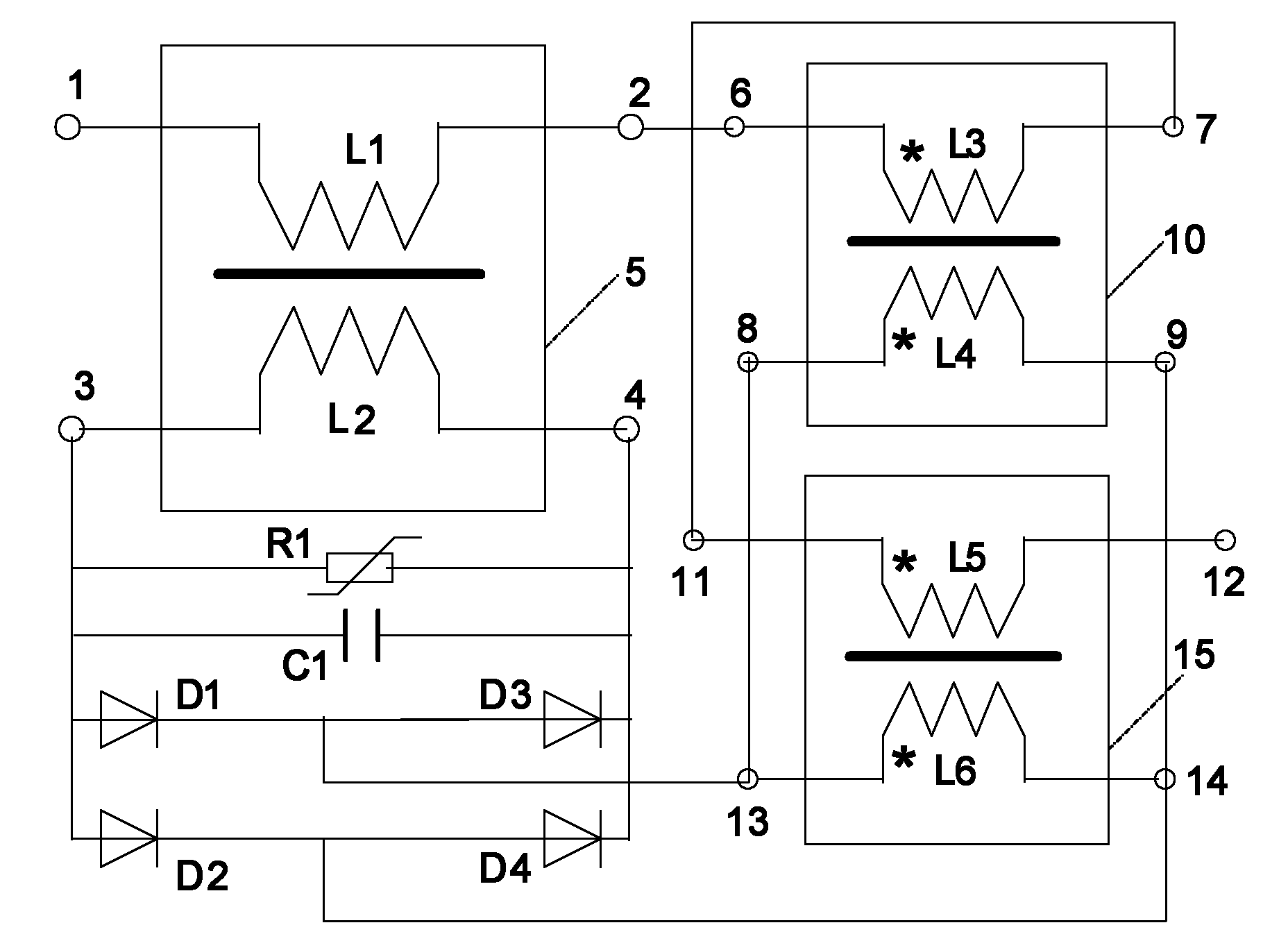
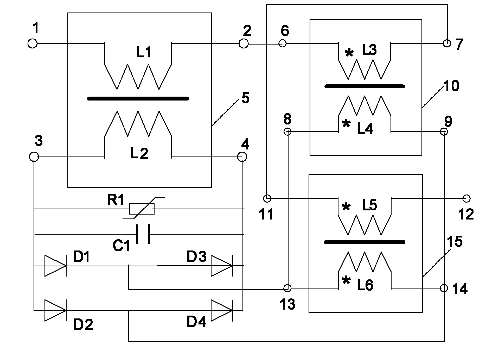
[0016] A current transformer controlled short-circuit current limiter such as figure 1 shown. Including the saturable reactor 5 composed of the reactance coil L1 and the DC coil L2, the reactance coil L1 and the DC coil L2 interact through the closed-loop iron core inside the saturable reactor 5; the current transformer composed of the primary coil L3 and the secondary coil L4 I10; a current transformer II15 composed of a primary coil L5 and a secondary coil L6.

[0017] The reactance coil terminal II2 of the reactance coil L1 is connected in series with the current transformer I primary coil terminal I6 of the primary coil L3, and the current transformer I primary coil terminal II7 of the primary coil L3 is connected in series with the current transformer II primary coil terminal I11 of the primary coil L5; Reactance coil terminal I1 and current tran...


PUM


Abstract

The invention relates to a short circuit current limiter controlled by current transformers. A saturated reactor comprises a reactance coil L1 and a direct current coil L2, and the reactance coil L1 and the direct current coil L2 perform interaction through a closed-loop iron core in the saturated reactor; the current transformer I comprises a primary coil L3 and a secondary coil L4; the current transformer II comprises a primary coil L5 and a secondary coil L6; the reactance coil L1, the coil L3 of the current transformer and the coil L5 are connected in series, and the reactance coil L1 andretaining terminals in the primary coils of the current transformers are used as input and output terminals of a device; the secondary coils of the two current transformers are connected in parallel and then connected with the two input ends of a full-bridge rectification circuit; and the output end of the rectification circuit is connected with the direct current coil L2 in series so as to form a closed loop. A piezoresistor R1 and a capacitor C1 are further connected at two ends of the direct current coil L2 in parallel.

Description

technical field [0001] The invention relates to the technical field of power transmission and transformation in power systems, in particular to a short-circuit current limiter controlled by a current transformer. Background technique [0002] With the continuous development of the power system and the continuous increase of power generation capacity, the short circuit current caused by the short circuit of the power system is very large. The short circuit current caused by the short circuit in the power system is very harmful to the power system. Therefore, reducing the short-circuit current can reduce the damage degree of the power equipment during short-circuit and improve the stability of the power system. [0003] In recent years, research on methods and devices for limiting short-circuit current (also known as short-circuit current limiters) has become a hot topic. [0004] Invention patent No.: 2003101235398 "Superconducting Saturated Core Fault Current Limiter" prop...

Claims


Application Information

Patent Timeline
Patent Type & Authority Applications(China)
IPC IPC(8): H02H9/02
Inventor 李晓明
Owner SHANDONG UNIV
Why Eureka
Try Eureka