fall protection system

A technology of drop protection, pulleys, applied in the field of systems

Inactive Publication Date: 2011-12-14
FALLSAFE TECH PTY LTD
View PDF2 Cites 13 Cited by
  • Summary
  • Abstract
  • Description
  • Claims
  • Application Information

AI Technical Summary

Problems solved by technology

This is complicated because means of accessing fallen workers include rope rescues, high-angle ladder rescues, or other classes of special approaches

Method used


Image

  • fall protection system
  • fall protection system
  • fall protection system

Examples


Embodiment Construction

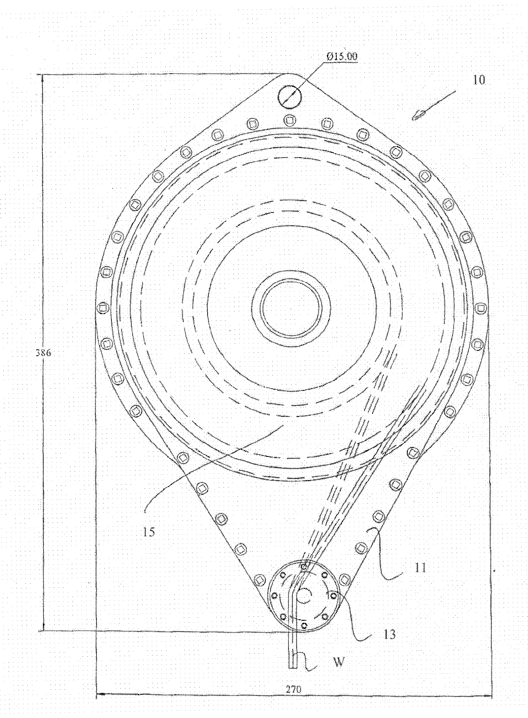
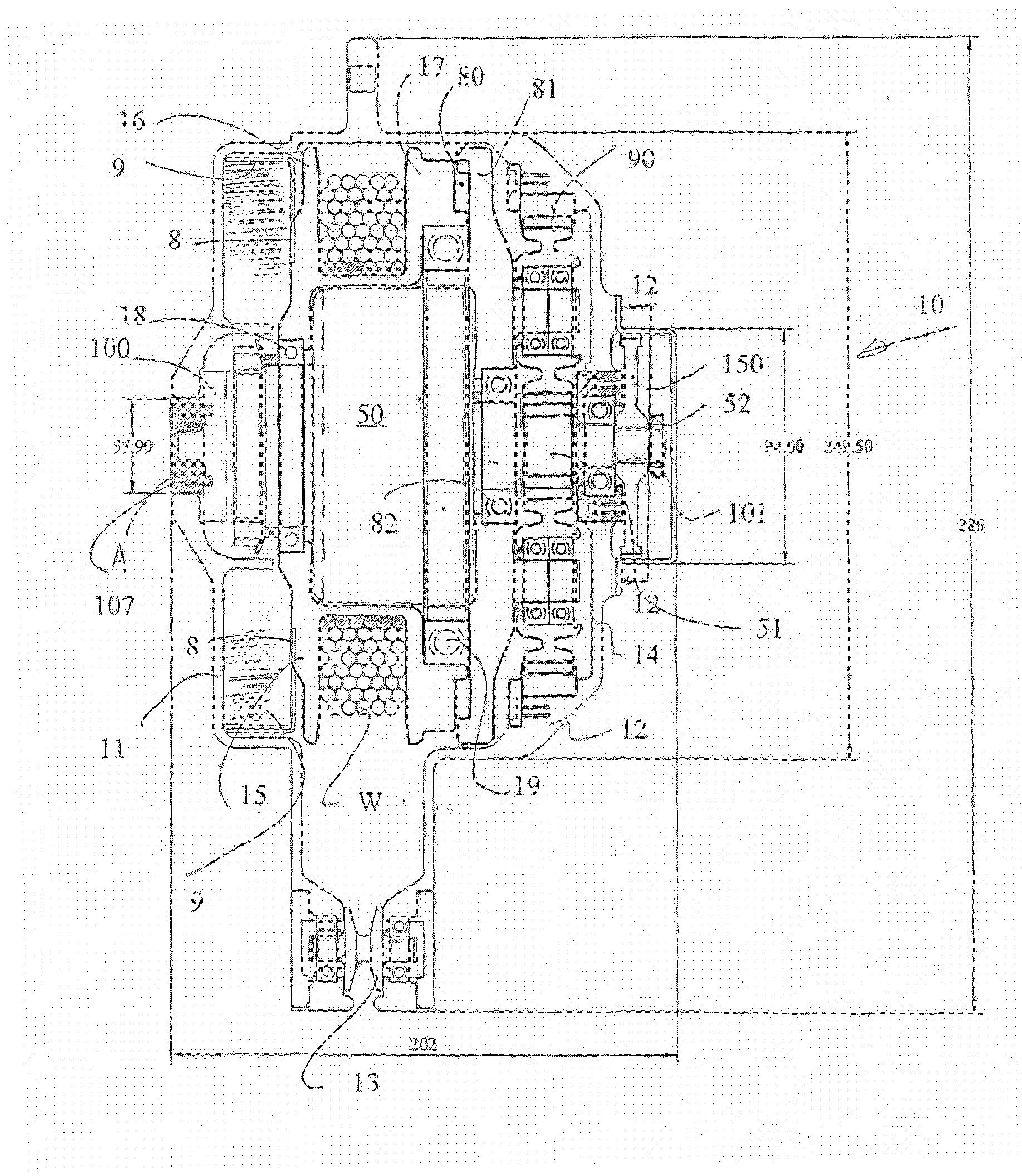
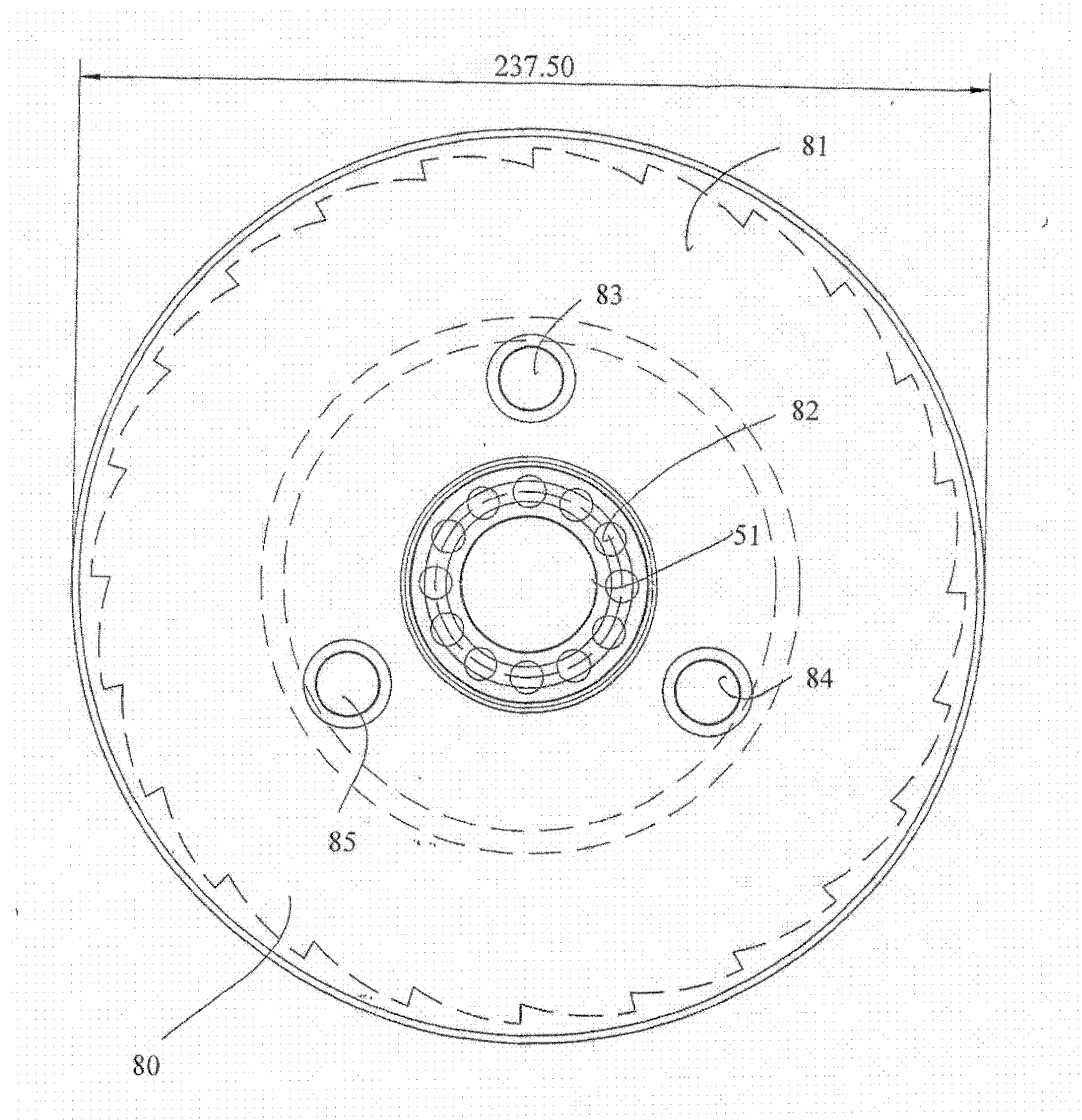
[0031] The arresting and lowering device 10 shown in the figures basically comprises a two-part housing 11, 12 comprising a pulley 15 on which a rope W is wound. At low speeds, the pulley 15 is free to rotate relative to the flat coil spring 9, which is located in the cavity of the housing part 11, thereby providing light back tension to the rope W. At high speeds, such as occurs in free fall within 600 mm, the centrifugal clutch 80 is activated, engaging the hydraulic actuator 50 mounted in the center of the pulley 15 . The actuator 50 controls the rotation of the pulley 15 through an epicyclic train 90 .

[0032] In use, the cord W is connected to a harness worn by the user of the device in such a way that it can be unwound from the pulley 15 at low cord tension and speed relative to the spring 9 . This allows the user to move flexibly relative to the device while being connected to the device by the length of the cord W. Should the user fall, the sudden acceleration of th...


PUM


Abstract

A fall protection system comprising a line wound onto a rotatable pulley having a centrifugal clutch which activates a gearbox which in turn drives an input shaft of a hydraulic actuator whereby the hydraulic actuator controls the rate of rotation of the pulley, and a secondary brake which slows the rotational speed of the pulley should it exceed a predetermined speed, whereby in use, the line isattached to a user to restrain a fall and then the system facilitates unwinding of the line at a controlled speed to effect descent.

Description

technical field [0001] The present invention relates to personal fall protection systems, and in particular to a system that has the dual role of arresting a fall while providing vertical descent and self-rescue capabilities after arresting the fall. Background technique [0002] A number of proposals have been made for minimizing injuries to the human body caused by falls from great heights. This is a difficult problem in construction, heavy industry, offshore oil and gas extraction, and aircraft and mining vehicle maintenance, where personnel are at risk of falling to lower water or ground level. Current statutory regulations state that generally a fall threat of 2 meters requires a fall protection or guard. Given the potential height differences that occur in the industries mentioned above, fall hazard control is often required. One solution to the above-mentioned problem is to attach the human body to a harness, which in turn is attached to a fall arrester secured to t...

Claims


Application Information

Patent Timeline
Patent Type & Authority Applications(China)
IPC IPC(8): A62B1/12A62B1/10F16D59/00F16D57/06
CPCF16D2127/002F16D51/22A62B35/0093
Inventor 斯蒂芬·格林
Owner FALLSAFE TECH PTY LTD
Why Eureka
Try Eureka