High Speed ​​Vacuum DC Current Limiting Circuit Breaker

A circuit breaker, high-speed technology, used in high-voltage air circuit breakers, high-voltage/high-current switches, circuits, etc., can solve the problems of inability to break short-circuit current, lack of current limiting ability, etc., to achieve fast action speed and small fault current. , the effect of derating

Inactive Publication Date: 2011-12-21
NAVAL UNIV OF ENG PLA
View PDF4 Cites 27 Cited by
  • Summary
  • Abstract
  • Description
  • Claims
  • Application Information

AI Technical Summary

Problems solved by technology

[0005] This method has the advantages of simple structure and easy implementation. However, since the circuit breaker adopting this principle will have a recovery voltage at the moment when the current crosses zero, in order to achieve sufficient dielectric insulation strength, the vacuum...

Method used


Image

  • High Speed ​​Vacuum DC Current Limiting Circuit Breaker
  • High Speed ​​Vacuum DC Current Limiting Circuit Breaker
  • High Speed ​​Vacuum DC Current Limiting Circuit Breaker

Examples


Embodiment Construction

[0022] The technical solution of the present invention will be described in detail below in conjunction with the accompanying drawings and specific embodiments.

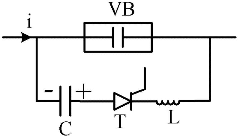
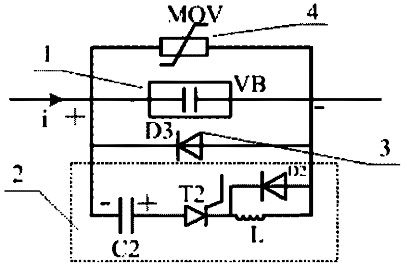
[0023] like figure 2 As shown, the high-speed vacuum DC current-limiting circuit breaker includes a high-speed vacuum contact mechanism 1 for quick opening when receiving an external command, a reverse current generation circuit 2 for creating a current zero-crossing point in the vacuum interrupter, and a The freewheeling circuit 3 for obtaining the zero voltage recovery time after the current in the vacuum interrupter crosses zero and the energy absorbing circuit 4 for absorbing the energy of the circuit, the high-speed vacuum contact mechanism 1, the reverse current generating circuit 2, continued The current circuit 3 and the energy absorbing circuit 4 are connected in parallel, and the energy absorbing circuit 4 may be a piezoresistor or other electronic components with energy absorbing function or a combination...


PUM


Abstract

The invention discloses a driving mechanism for a high-speed contact of a current-limiting circuit breaker, which comprises a frame in which an electromagnetic repulsion mechanism, a spring connection mechanism and a permanent magnet mechanism are fixedly installed in sequence; the electromagnetic repulsion mechanism includes parallel stacked repulsion drive The coil and the repulsion metal disk, the two ends of the repulsion driving coil are connected with the drive circuit for providing the driving current; the spring connection mechanism includes elastic parts arranged along the circumference of the repulsion metal disk; the permanent magnet mechanism includes a static iron core and a permanent magnet inlaid in the middle of the static iron core , the two sides of the permanent magnet are respectively equipped with an opening coil and a closing coil, a moving iron core is arranged between the permanent magnet and the magnetic poles of the static iron core, a moving contact driving rod is arranged in the moving iron core, and the moving contact driving rod The axial center portion passing through the static iron core, the spring connection mechanism, the repulsive force driving coil and the repulsive force metal disc in turn is connected with the contact of the circuit breaker. The invention has the advantages of short opening time, fast initial separation speed, high action reliability, long mechanical life and the like.

Description

technical field [0001] The invention relates to a current-limiting circuit breaker used in the event of a short-circuit fault in a DC power grid, in particular to a high-speed DC current-limiting circuit breaker based on the principle of forced zero-crossing shutdown of a vacuum interrupter. Background technique [0002] With the development of the national economy and the increase of urban electricity load, the demand for the capacity of the power system is getting higher and higher. Nowadays, DC transmission is increasingly used in developed countries such as the United States, Japan, and Germany. In addition, independent power systems such as modern ships and subways also use DC power systems. In order to limit the increasing DC short-circuit current and protect the safety of electrical equipment, DC limiters with stronger current limiting capabilities and higher reliability are urgently needed. flow breaker. [0003] Due to the ablation effect of the arc on the mechani...

Claims


Application Information

Patent Timeline
IPC IPC(8): H01H33/66H01H33/664H01H33/666
Inventor 庄劲武江壮贤刘路辉徐国顺王晨武瑾
Owner NAVAL UNIV OF ENG PLA
Why Eureka
Try Eureka