Structure of reversing valve

A reversing valve and valve cavity technology, applied in the field of multi-position multi-way reversing valve structure, can solve problems such as damage to piston and cylinder end cover, wear of piston and cylinder end cover, short service life of piston cylinder, etc. The effect of avoiding collision and wear, increasing resistance and prolonging service life

Inactive Publication Date: 2012-02-22
皇甫岳伟
View PDF4 Cites 9 Cited by
  • Summary
  • Abstract
  • Description
  • Claims
  • Application Information

AI Technical Summary

Problems solved by technology

Not only can it produce a lot of collision noise, but it will inevitably cause serious wear to the piston and cylinder end cover
After being used for a period of time, it will inevitably cause certain damage to the piston and the end cover of the cylinder body; the higher the pressure, the faster the speed, and the shorter the service life of the piston cylinder

Method used


Image

  • Structure of reversing valve
  • Structure of reversing valve
  • Structure of reversing valve

Examples


Embodiment 1

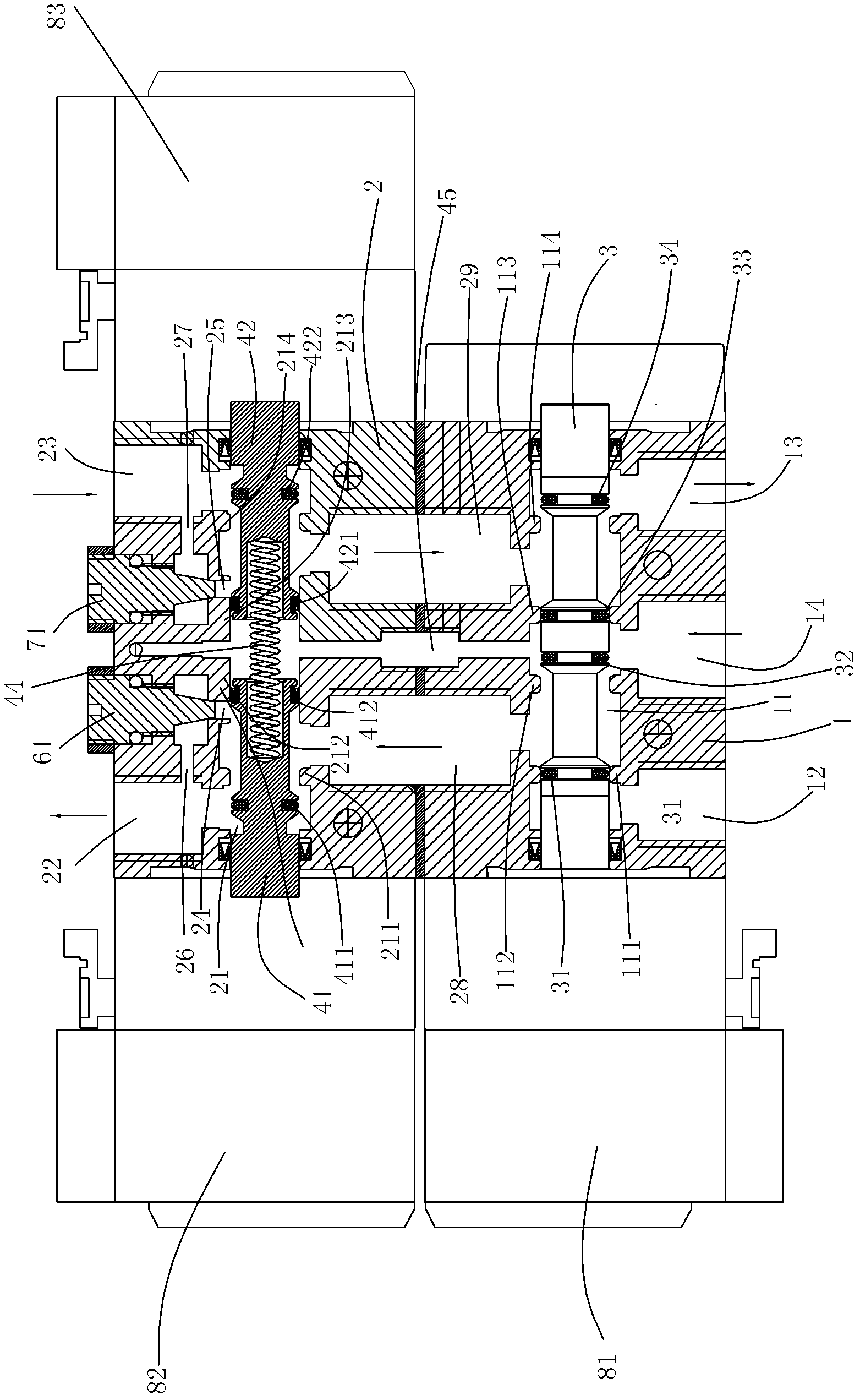
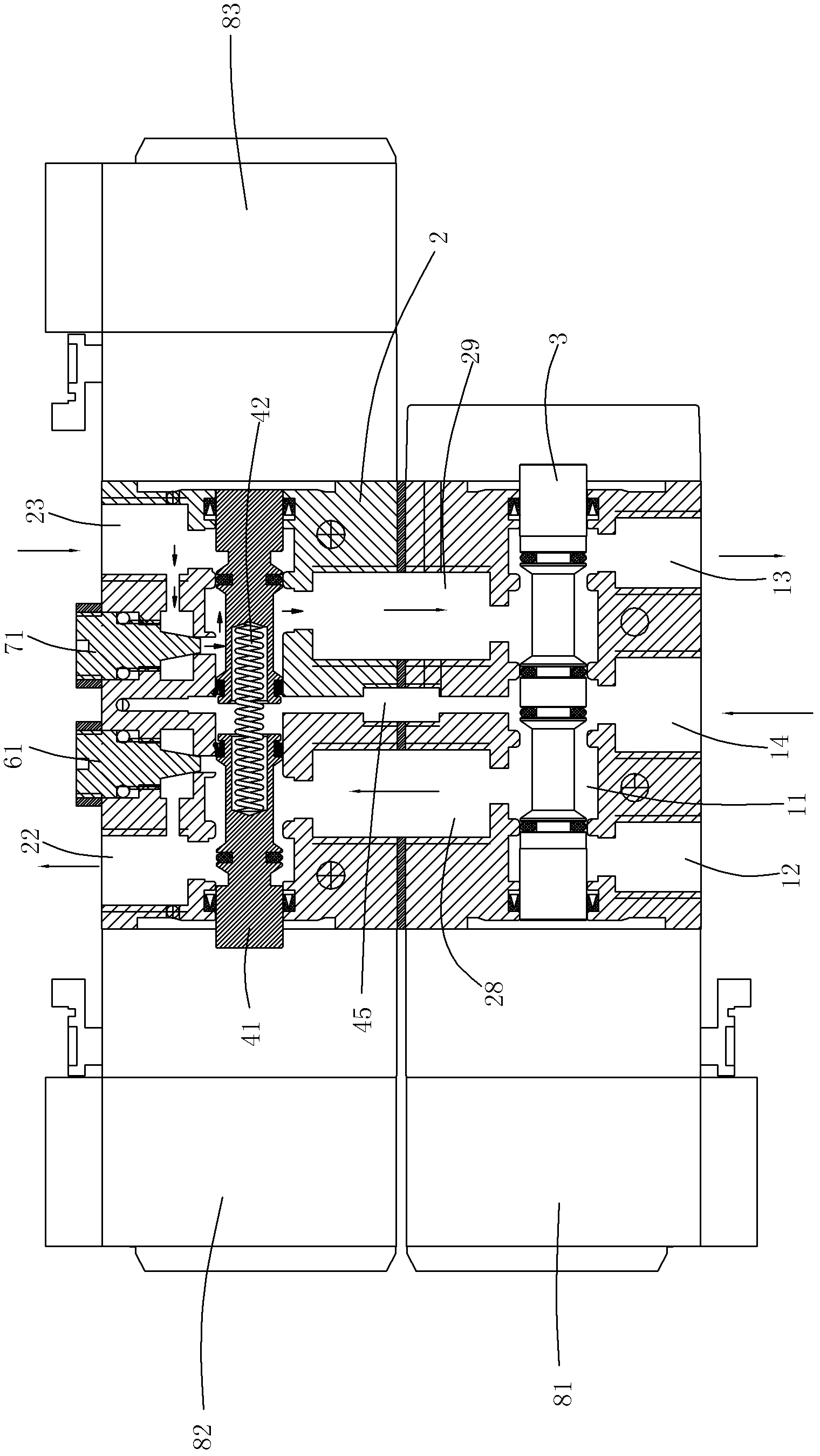
[0031] Such as figure 1 with figure 2 As shown, the reversing valve includes:

[0032] Considering the ease of processing and assembly, the valve body is designed as a split structure in this embodiment, including a first valve body 1 and a second valve body 2, the first valve body 1 and the second valve body 2 are connected together by screws . In this embodiment, the first valve body 1 and the second valve body 2 are superimposed and connected. The first valve body and the second valve body can also be connected side by side according to the installation space, such as Figure 5 Shown. And a sealing ring is arranged between the connecting channels of the two.

[0033] The above-mentioned first valve body 1 is provided with a first valve cavity 11 that accommodates the first valve stem 3 transversely therethrough, and a longitudinal first outlet 12 and an inlet 14 are spaced from left to right on the outer side wall of the first valve body. And the second outlet 13, the first o...

Embodiment 2

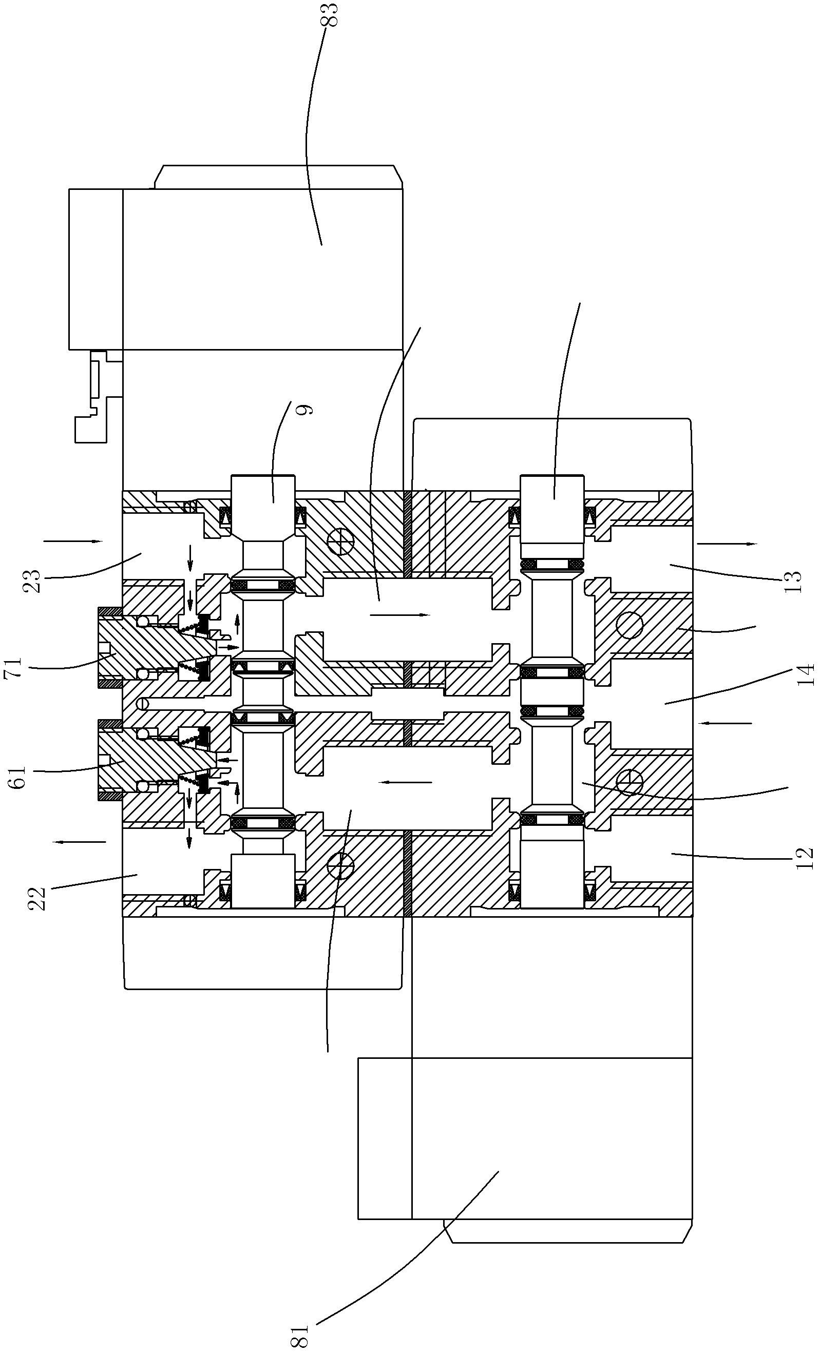
[0049] Such as image 3 , Figure 4 with Image 6 As shown, a second valve rod 9 is provided in the second valve cavity of the reversing valve structure to replace the second and third valve rods, and the fourth control valve 84 is drivingly connected to the second valve rod 9. The second valve body 2 is also provided with a first overflow hole 101 communicating the second valve cavity 21 and the first side flow hole 26, and a second overflow hole 101 communicating the second valve cavity 21 and the second side flow hole 27. The overflow hole 102; the first pressure piece 62 and the second pressure piece 72 are respectively shielded on the first overflow hole 101 and the second overflow hole 102; the first spring 63 and the second spring 64 are respectively looped around the first cone The two ends of the first spring 63 and the second spring 64 are in contact with the first pressure piece 62, the second pressure piece 72, the first tapered valve core 61, and the second tapered...


PUM


Abstract

The invention relates to a structure of a reversing valve. The reversing valve comprises a control reversing valve and an action reversing valve, and two groups are matched to realize flow velocity variable control over a pressure medium. Compared with the prior art, the structure of the reversing valve has the advantages that: through a design of a second valve rod and two overflow valves, when a piston moves to be about to contact the end of a piston cylinder, the reflux quantity of the pressure medium is reduced, and the motion resistance of the piston is increased, so that the motion velocity of the piston is reduced, the piston slowly touches the end of the piston cylinder, the piston and the end of the piston cylinder are prevented from being collided and worn when the piston moves at a high speed, the service life of the piston cylinder is effectively prolonged, and the operation safety and stability of the piston cylinder are ensured simultaneously.

Description

Technical field [0001] The invention relates to a multi-position multi-way reversing valve structure. Background technique [0002] When the piston cylinder is working at high speed or high pressure, the movement speed of the piston rod and piston is very fast. In this way, when the piston quickly moves to the two extreme positions of the front and rear ends of the cylinder, the end caps of the piston and the cylinder are inevitably required. Collision. Not only can it produce a lot of collision noise, but it will inevitably cause serious wear on the piston and cylinder end cover. After using for a period of time, the piston and cylinder end cover will inevitably cause certain damage; the higher the pressure, the faster the speed, and the shorter the service life of the piston cylinder. Summary of the invention [0003] The technical problem to be solved by the present invention is to provide a reversing valve structure capable of making the piston perform variable-speed movemen...

Claims


Application Information

Patent Timeline
Patent Type & Authority Applications(China)
IPC IPC(8): F16K11/10
Inventor 皇甫岳伟
Owner 皇甫岳伟
Why Eureka
Try Eureka