Die for casting dry type transformer coil

A technology for dry-type transformers and moulds, which is applied in the manufacture of coils, etc., which can solve the problems that the machining accuracy of lathes and milling machines cannot meet the technical requirements, increase mold processing costs and processing cycles, and limit the processing distance of milling machines, etc., to reduce clamping , reduce vibration, reduce the effect of processing difficulty

Inactive Publication Date: 2012-02-22
QINGDAO TRANSFORMER GRP CO LTD
View PDF0 Cites 2 Cited by
  • Summary
  • Abstract
  • Description
  • Claims
  • Application Information

AI Technical Summary

Problems solved by technology

Taking the high-voltage coil casting mold of a dry-type transformer with a capacity of 1600kva as an example, the traditional casting mold processing method is as follows: the height of the mold is 1420mm, and there are sealing grooves on the contact surfaces of the left and right half shells, with high-temperature resistant silicone rubber strips for sealing. The left and right half shells are connected by bolts to form a complete casting mold; the contact surface of the two half shells is the sealing surface, and its surface roughness requirement is 1.6, which needs to be finished with a milling machine. Because the mold height is too high, the processing distance of the milling machine is limited (The maximum processing length of universal lifting table milling machine X6132 is 1320), it is difficult to guarantee its processing accuracy
After the two half-shells are connected, it is necessary to use a lathe to process the inner cavity of the half-shell. The surface roughness of the inner cavity is required to be 0.8, and because the workpiece is too long, it is easy to vibrate and affect the processing effect of the lathe. Generally, the lathes owned by enterprises and The machining accuracy of the milling machine cannot meet the technical requirements, and the required molds can only be processed outsourced by units with large lathes and milling machines, which greatly increases the processing cost and cycle time of the molds

Method used


Image

  • Die for casting dry type transformer coil
  • Die for casting dry type transformer coil
  • Die for casting dry type transformer coil

Examples


Embodiment Construction

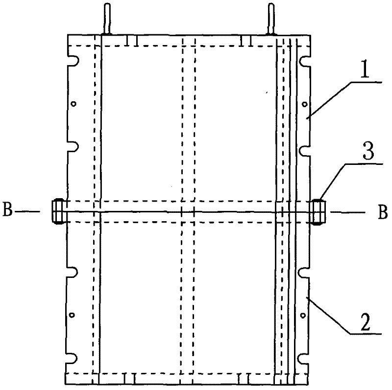
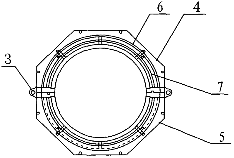
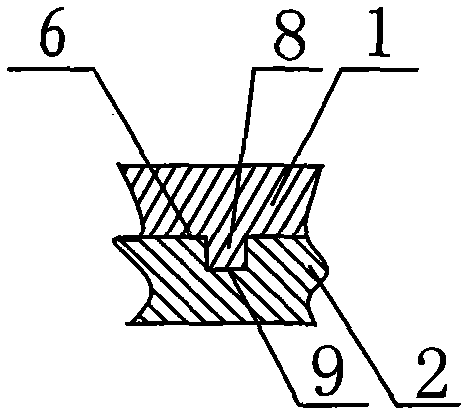
[0012] Such as figure 1 , 2 As shown in and 3, a dry-type transformer coil casting mold is composed of a left half-shell 4 and a right half-shell 5. Bolts I connect the left half-shell 4 and the right half-shell 5 into one body, and the left half-shell 4 and the right half-shell 5 There is a sealing groove Ⅰ on the contact surface, and the sealing groove Ⅰ is sealed with a high-temperature-resistant silicone rubber strip; the mold is also divided into two parts, the upper part 1 and the lower part 2, which are connected as one by bolts Ⅱ3; the upper part 1 and the lower part The surface roughness of the contact surface of 2 is 1.6, and the corresponding sealing groove II7 is opened on the contact surface. The sealing groove II7 has a built-in high-temperature resistant silicone rubber strip for sealing; a positioning connection part 6 is set outside the sealing groove II7, and the The positioning connection part 6 includes a left half-shell connection part and a right half-sh...


PUM


Abstract

The invention relates to a die for casting a dry type transformer coil. The die consists of a left semi-shell and a right semi-shell which are connected into a whole through bolts, wherein sealing grooves are formed on contact surfaces of the left semi-shell and the right semi-shell; and a high-temperature-resistant silicon rubber strip is placed in each sealing groove for sealing. The invention is characterized in that: the die is equally divided into an upper part and a lower part which are connected into a whole through the bolts; corresponding sealing grooves are formed on the contact surfaces of the upper part and the lower part; the high-temperature-resistant silicon rubber strip is placed in each sealing groove for sealing; and a positioning connecting part is arranged on the outer side of each sealing groove. The circular degree, coaxiality and smoothness of the die can be guaranteed so that the range of equipment for processing the die is expanded, processing difficulty is reduced, processing period is shortened, processing cost is reduced and quality of the cast coil is guaranteed.

Description

technical field [0001] The invention relates to a casting mold, in particular to a casting mold for dry-type transformer coils, which belongs to the technical field of transformer special mechanical equipment. Background technique [0002] After the cast type dry transformer coil is assembled with the casting mold, it is poured in the vacuum pouring equipment. When pouring dry-type transformer coils, as the capacity increases, the height of the coils also increases, which increases the height of the casting mold used, which increases the difficulty of mold processing. Taking the high-voltage coil casting mold of a dry-type transformer with a capacity of 1600kva as an example, the traditional casting mold processing method is as follows: the height of the mold is 1420mm, and there are sealing grooves on the contact surfaces of the left and right half shells, with high-temperature resistant silicone rubber strips for sealing. The left and right half shells are connected by bo...

Claims


Application Information

Patent Timeline
Patent Type & Authority Applications(China)
IPC IPC(8): H01F41/04B29C39/26
Inventor 张式雷
Owner QINGDAO TRANSFORMER GRP CO LTD
Why Eureka
Try Eureka