Brake device for vehicle

A brake device and vehicle technology, which is applied in the direction of control devices, brakes, brake components, etc., can solve the problem of deterioration of brake feel and achieve the effect of preventing the decline of brake feel

Active Publication Date: 2012-02-22
HONDA MOTOR CO LTD
View PDF4 Cites 9 Cited by
  • Summary
  • Abstract
  • Description
  • Claims
  • Application Information

AI Technical Summary

Problems solved by technology

[0006] In the BBW type brake device, the brake hydraulic pressure for hydraulic braking is generated by the slave hydraulic cylinder operated by the electric motor. There is a time lag until the piston starts to move in the cylinder, and even if the piston starts to move in the cylinder, there is a time lag until the brake hydraulic pressure is generated due to the deformation of the cup seal provided on the piston. Therefore, at time t2, The hydraulic braking force will not increase smoothly, and shortly after time t2, the total braking force may temporarily decrease relative to the target braking force, which will deteriorate the braking feel

Method used


Image

  • Brake device for vehicle
  • Brake device for vehicle
  • Brake device for vehicle

Examples


no. 1 approach

[0037] first embodiment

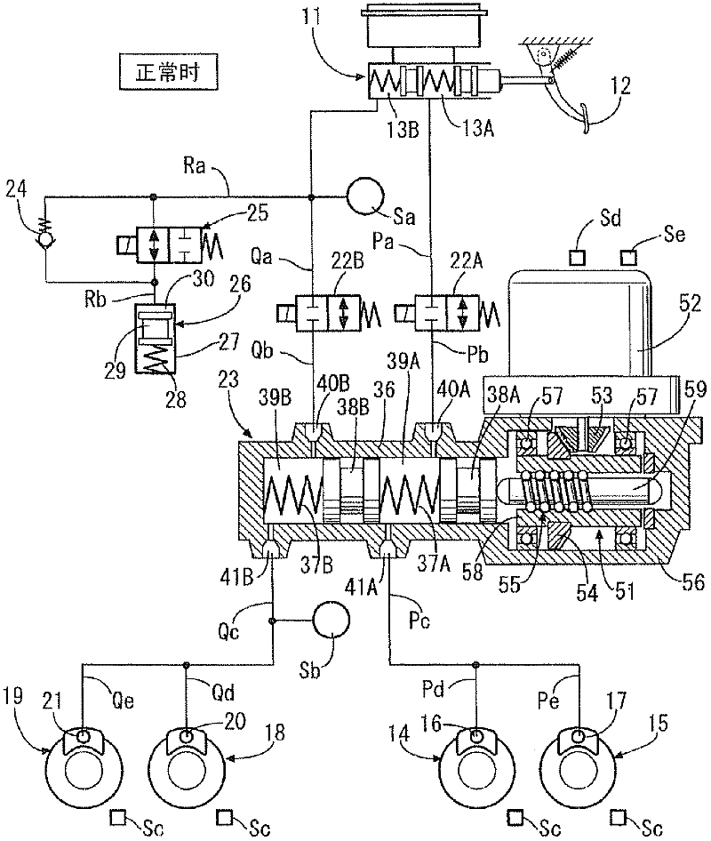
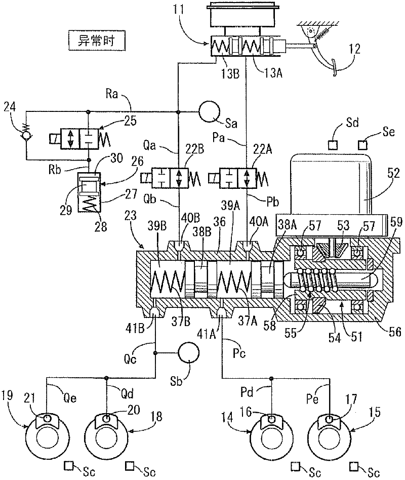
[0038] like figure 1 As shown, the tandem-type master hydraulic cylinder 11 is provided with a sub-hydraulic chamber 13A and a main hydraulic chamber 13B that output brake hydraulic pressure corresponding to the driver's depressing force on the brake pedal 12, and the sub-hydraulic chamber 13A passes through the hydraulic passages Pa, Pb . Qe is connected to the wheel cylinders 20, 21 of the disc brake devices 18, 19 of the right front wheel and the left rear wheel, for example.

[0039] An on-off valve 22A as a normally open electromagnetic valve is arranged between the liquid paths Pa and Pb, and an on-off valve 22B as a normally open electromagnetic valve is arranged between the liquid paths Qa and Qb. A slave hydraulic cylinder 23 is arranged between the hydraulic paths Pc and Qc. Further, the stroke simulator 26 is connected to the fluid passages Ra and Rb branched from the fluid passage Qa extending from the main hydraulic chamber 13B via a ...

no. 2 approach

[0061] In the first embodiment, when performing regenerative braking, the slave hydraulic cylinder 23 must be driven to eliminate the dead stroke, but if the driver returns the brake pedal 12 before the vehicle speed drops below the replacement starting speed, the slave hydraulic cylinder 23 will be driven back. The hydraulic braking by the cylinder 23 is no longer performed, so the driving of the slave hydraulic cylinder 23 for eliminating the lost stroke may be useless.

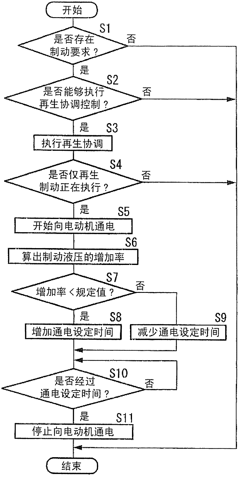
[0062] Figure 4 The flow chart of the second embodiment shown can eliminate the above-mentioned problems, so image 3 Step S4A is added after step S4 in the flow chart of . That is, when only regenerative braking is being performed in step S4, if the vehicle speed detected by the vehicle speed sensor Sc in step S4A is lower than the replacement preparation start vehicle speed which is slightly higher than the replacement start vehicle speed, the vehicle is driven in steps S5 to S11. The slave hydraulic c...


PUM


Abstract

Even when a slave cylinder is operated by driving an electric motor simultaneously with the start of the reduction of regenerative braking force at a time (t3) at which the vehicle speed drops below a shift start vehicle speed and switching from regenerative braking to hydraulic braking is performed, the rise of hydraulic braking force is delayed by the ineffective stroke of the slave cylinder, and therefore a temporary drop in the total braking force of the regenerative braking force and the hydraulic braking force occurs. However, by eliminating the ineffective stroke of the slave cylinder by slightly driving the electric motor in advance at a time (t2) at which the vehicle speed drops below a shift preparation start vehicle speed, the temporary drop in the total braking force of the regenerative braking force and the hydraulic braking force is prevented from occurring at the time of the switching, so that a reduction in brake feeling can be prevented.

Description

technical field [0001] The present invention relates to a brake device for a vehicle capable of regenerative braking and hydraulic braking, that is, to a brake device for a vehicle provided with an electric brake hydraulic pressure generating device for generating brake hydraulic pressure for hydraulic braking . Background technique [0002] According to the following patent document 1, there is known a BBW (brake-by-wire) type brake device in which the operation of the brake pedal by the driver is converted into an electric signal, and the slave that operates based on the electric signal The brake hydraulic pressure generated by the hydraulic cylinder activates the wheel brake cylinder, and as a backup when the slave hydraulic cylinder fails, a master hydraulic cylinder that operates through the brake pedal is installed. When the slave hydraulic cylinder is normal, the stroke simulator is used to Absorbs the brake fluid sent by the master hydraulic cylinder, thereby enabli...

Claims


Application Information

Patent Timeline
Patent Type & Authority Applications(China)
IPC IPC(8): B60T8/00B60L7/10B60T8/17B60L7/24
CPCB60L7/18B60L7/24B60L7/26B60L2240/12B60T1/10B60T8/4081B60T13/586B60T13/662B60T13/686B60T2270/604
Inventor 松下悟史
Owner HONDA MOTOR CO LTD
Why Eureka
Try Eureka