Vehicle braking apparatus

A brake device and wheel brake cylinder technology, which is applied in the direction of brake transmission device, brake action activation device, brake, etc., can solve the problems of inability to ensure responsiveness, limit of motor miniaturization, etc., and achieve small size and light weight , Reduce the maximum load torque and improve the responsiveness

Active Publication Date: 2015-03-25
HONDA MOTOR CO LTD
View PDF4 Cites 0 Cited by
  • Summary
  • Abstract
  • Description
  • Claims
  • Application Information

AI Technical Summary

Problems solved by technology

[0004] However, in the above-mentioned prior art, the rotational speed is increased by performing weak field control on the electric motor, so that the driving speed of the piston of the slave hydraulic cylinder is increased, so that the responsiveness of the brake hydraulic pressure can be improved to a certain extent, but in avoiding In emergency situations such as collisions, it is inevitable that sufficient responsiveness cannot be ensured, so there is a limit to the miniaturization of the motor of the slave hydraulic cylinder

Method used


Image

  • Vehicle braking apparatus
  • Vehicle braking apparatus
  • Vehicle braking apparatus

Examples


no. 1 approach

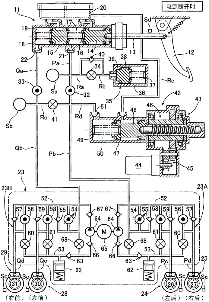
[0056] Such as figure 1 As shown, the tandem master cylinder 11 includes a first piston 14 connected to a brake pedal 12 operated by the driver via a push rod 13 and a second piston 15 arranged in front of the first piston 14. The first hydraulic chamber 17 in which the return spring 16 is accommodated between the one piston 14 and the second piston 15 is divided, and the second hydraulic chamber 19 in which the return spring 18 is accommodated in front of the second piston 15 is divided. The first hydraulic chamber 17 and the second hydraulic chamber 19 that can communicate with the reservoir 20 are provided with a first output port 21 and a second output port 22, respectively. The first output port 21 passes through the fluid paths Pa, Pb, and VSA (Vehicle Stability Assist) The device 23 and the fluid passages Pc, Pd are connected to, for example, the wheel cylinders 26, 27 (first system) of the left and right rear disc brake devices 24, 25, and the second output port 22 is co...


PUM


Abstract

A vehicle braking system includes an operation amount detector, a hydraulic pressure source, a controller, and a wheel cylinder. The hydraulic pressure source is to generate brake hydraulic pressure corresponding to an amount of operation detected by the operation amount detector. The wheel cylinder is to be operated by the brake hydraulic pressure generated by the hydraulic pressure source. The hydraulic pressure source includes a first actuator and a second actuator. The first actuator includes a piston and an electric motor. The electric motor is configured to move the piston forwardly to generate the brake hydraulic pressure. The second actuator includes a pump configured to pressurize brake fluid located downstream of the first actuator. The controller is configured to selectively operate the first actuator and the second actuator based on the amount of operation detected by the operation amount detector.

Description

Technical field [0001] The present invention relates to a brake device for a vehicle, including: an operation amount detection mechanism that detects an operation amount of a brake pedal; and a hydraulic pressure source that generates brake hydraulic pressure corresponding to the operation amount detected by the operation amount detection mechanism; A control mechanism that controls the operation of the hydraulic pressure source; wheel brake cylinders that operate by the brake hydraulic pressure generated by the hydraulic pressure source. Background technique [0002] According to the following Patent Document 1, there is known a BBW (brake-by-wire) type vehicle brake device in which the cost of the motor is reduced in order to reduce the size of the electric motor. The hydraulic cylinder is activated, and at the same time, the responsiveness of the brake hydraulic pressure is improved, and the electric motor is controlled by weak excitation to increase the speed. [0003] [Patent...

Claims


Application Information

Patent Timeline
Patent Type & Authority Patents(China)
IPC IPC(8): B60T13/66
CPCB60T17/22B60T13/662B60T13/745B60T13/686B60T8/442B60T7/042B60T8/4081
Inventor 岛田贵史
Owner HONDA MOTOR CO LTD
Why Eureka
Try Eureka