AI technical title is built by Patsnap AI team. It summarizes the technical point description of the patent document.
A technology of fixing device and guide rail, applied in the field of guide rail, can solve problems such as guide rail detachment
Active Publication Date: 2012-05-30
PAUL HETTICH
View PDF5 Cites 2 Cited by
Summary
Abstract
Description
Claims
Application Information
AI Technical Summary
This helps you quickly interpret patents by identifying the three key elements:
Problems solved by technology
Method used
Benefits of technology
Problems solved by technology
[0005] Under extremely unfavorable external conditions and when using high forces and taking into account the possibility of deformation, it is at least conceivable in the prior art that the guide rails could be unintentionally detached from the relevant rods
Method used
Image
Click on the blue label to locate the original text in one second.
Reading with bidirectional positioning of images and text.
Examples
Embodiment Construction
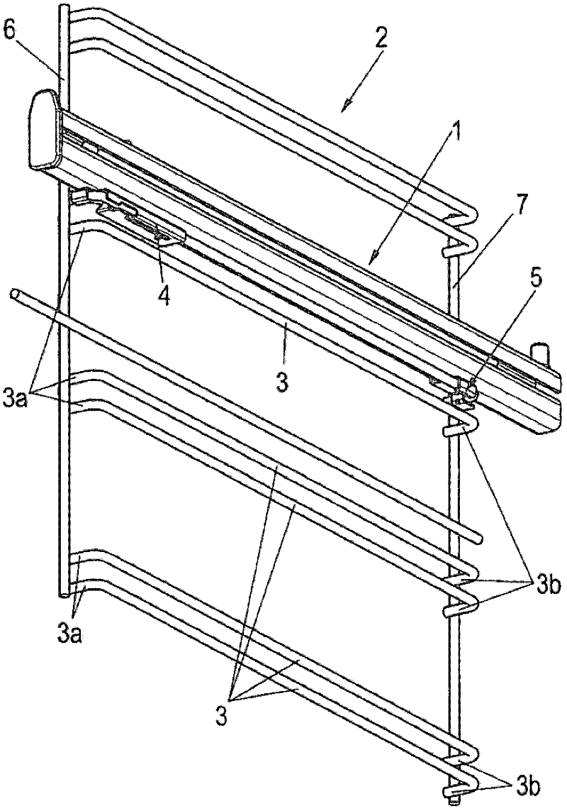
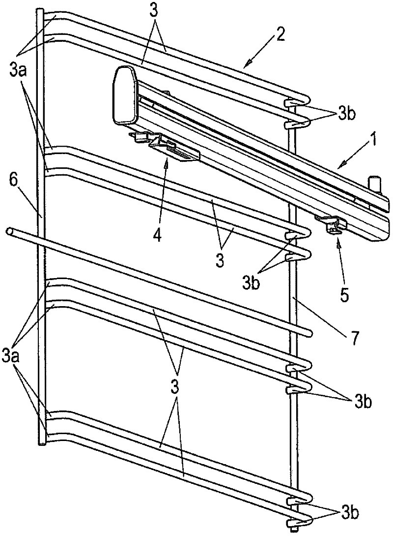
[0025] In the figures, the guide rails are designated generally by the reference numeral 1 and the lattice-shaped side part is generally designated by the reference numeral 2 , wherein the side part 2 has a plurality of horizontally extending bars 3 which are each provided with curved end regions 3a and 3b. For this purpose, the curved end regions 3 a are respectively situated at the front ends of the respective rods 3 and the respective end regions 3 b are respectively situated at the rear ends of the respective rods 3 .
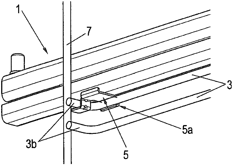
[0026] The guide rail 1 is provided on its underside with a quick-fixing device, which comprises two holding elements 4 and 5 which are fastened in the respective end regions of the guide rail 1, for which purpose the holding element designated with the reference number 4 is located in the guide rail 1, and the retaining element indicated by reference numeral 5 is at the rear end of the guide rail 1.
[0027] particularly evident in Figure 6 and Figure...
PUM
Abstract
The invention relates to a guide rail (1) that can be mounted on bars (3) of a grid-like side part (2) of a baking oven, a dishwasher, or similar items of furniture, said bars running horizontally and bent at an angle in the end region (3a, 3b), said rail having a quick fastening device made of two mounting elements (4, 4', 5) attached in the end regions of the guide rail (1) and that can be fixed on a bar (3) of a grid-like side part (2), and comprising a first and second mounting segment (4a, 4b, 5a, 52, 53) partially enclosing a bar (3) in the longitudinally extending region thereof and at the bent end regions (3a, 3b) thereof respectively, wherein the mounting segment (52, 53) facing the rear, bent end region (3b) is open in the direction toward the back side of the guide rail (1), so that the guide rail (1) can be slid onto and attached to one of the bars (3), starting from the front side of the side grid (2). In addition the front mounting element (4, 4') comprises a spring-loaded catch lug (42) in the mounting segment (4a) thereof partially enclosing a bar (3) in the longitudinally extending region thereof at a leg (40) located below a bar (3) and extending upward therefrom, said lug engaging behind the bar (3) enclosed by the mounting element in the assembled position of the guide rail (1), wherein the upper, free end (43) of the catch lug (42) protrudes into an aperture (44) of the leg (41) of the front mounting element (4, 4') overlapping the top side of the bar (3).
Description
technical field [0001] The invention relates to a guide rail, which can be fastened to a horizontally extending bar bent at an angle in the end region of a grid-shaped side part of an oven, dishwasher or similar furniture part, which guide rail has a quick fixing device, The rapid fastening device comprises two retaining elements fastened to the end region of the guide rail, which can be fastened detachably to a rod of the lattice-shaped side part and each have a part in the region of the longitudinal extension of the rod. A first retaining part surrounding the rod and a second retaining part partially surrounding the rod in each curved end region of the rod, wherein the retaining part of the rear retaining element is assigned to the curved rear end region Open towards the rear of the guide rail, so that the guide rail can be moved from the front side of the side grille to one of the rods by means of a quick fixing device and fastened to one of the rods, and the front retainin...
Claims
Application Information
Patent Timeline
Application Date:The date an application was filed.
Publication Date:The date a patent or application was officially published.
First Publication Date:The earliest publication date of a patent with the same application number.
Issue Date:Publication date of the patent grant document.
PCT Entry Date:The Entry date of PCT National Phase.
Estimated Expiry Date:The statutory expiry date of a patent right according to the Patent Law, and it is the longest term of protection that the patent right can achieve without the termination of the patent right due to other reasons(Term extension factor has been taken into account ).
Invalid Date:Actual expiry date is based on effective date or publication date of legal transaction data of invalid patent.

