Numerical control milling machine for curved surface machining of wood

A curved surface processing and CNC milling machine technology, which is applied in the direction of wood processing equipment, manufacturing tools, special forming/shaping machines, etc., can solve the problems of poor flexibility, complex structure design, and inability to process different types, so as to achieve diverse wood shapes and wood materials. Smooth processing and wide application range

Inactive Publication Date: 2012-06-20
博罗县昶丰精密机械设备有限公司
View PDF6 Cites 11 Cited by
  • Summary
  • Abstract
  • Description
  • Claims
  • Application Information

AI Technical Summary

Problems solved by technology

In the existing woodworking equipment that can process curved surfaces, the cutter head seat for installing the cutter head is generally arranged on the upper part of the main frame, which can be moved up and down or translated in the horizontal plane. The wood is fixed on the table of the main frame, and the table is movable or In this kind of curved surface processing equipment, generally multiple cutter heads are installed on the cutter head seat at the same time, each cutter head cannot be independently controlled, and the flexibility is poor. In one processing, only one kind of the same curved surface can be processed, and the same curved surface cannot be processed. The workpiece is processed with different curved surfaces; moreover, due to the needs of the motion trajectory of the tool head seat and the work table, the structural design is relatively complicated and the cost is high
In addition, during the processing of the existing wood processing equipment, the sawdust generated by the wood is flying everywhere, and it is easy to fall into the equipment, which not only affects the workshop environment, but also easily damages the equipment, affecting the normal operation and service life of the equipment.

Method used


Image

  • Numerical control milling machine for curved surface machining of wood
  • Numerical control milling machine for curved surface machining of wood
  • Numerical control milling machine for curved surface machining of wood

Examples


Embodiment Construction

[0019] The present invention will be further described below with reference to specific embodiments and accompanying drawings.

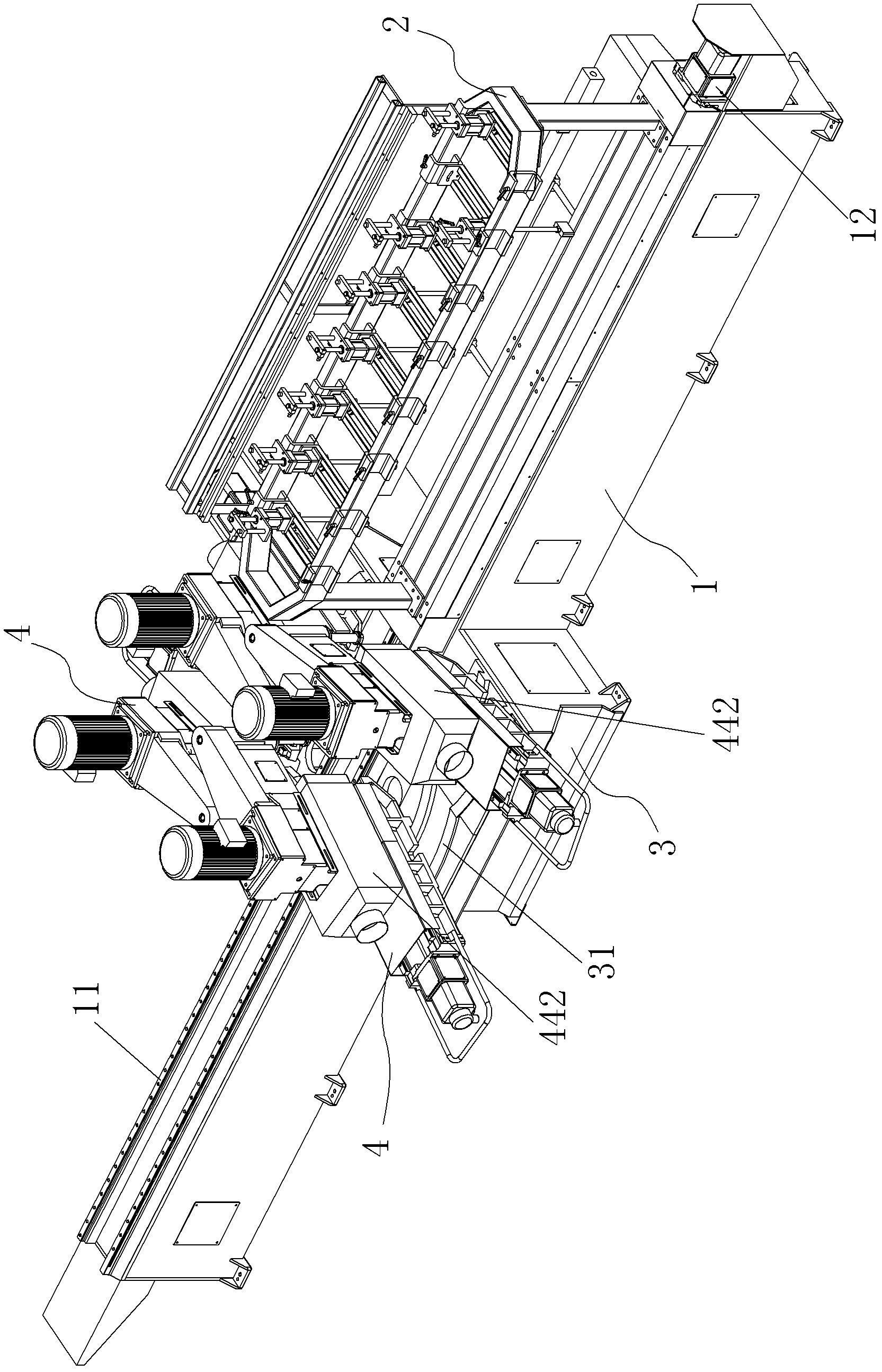
[0020] The CNC milling machine for wood surface processing according to the present invention includes a main frame 1 and an electrical console, and the main frame 1 and the electrical console can be integrated or separated. The split type is adopted in this embodiment.

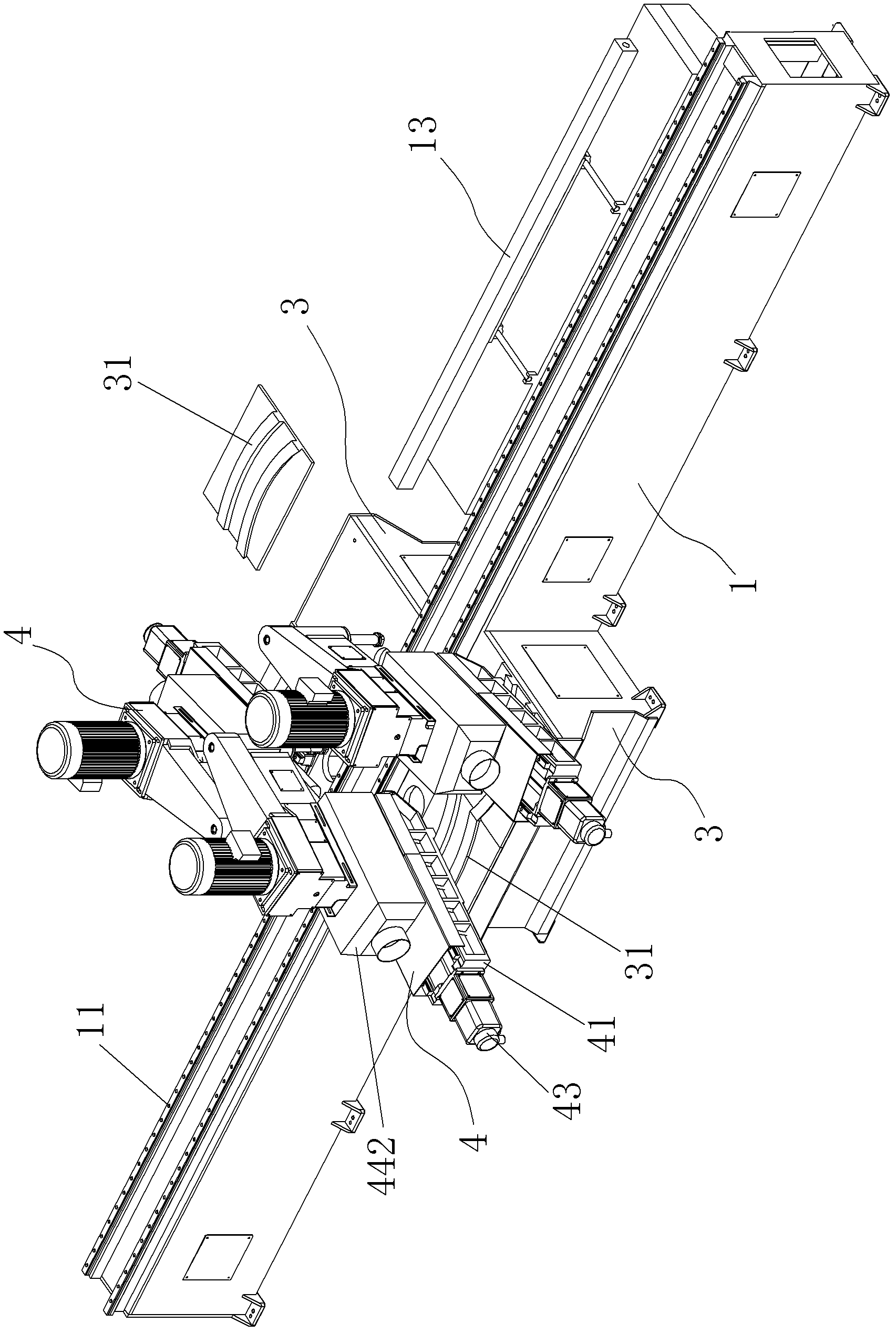
[0021] combine Figure 1 ~ Figure 3 As shown, a first linear slide rail 11 and a first servo motor drive mechanism 12 are provided along the length direction of the main frame 1, and a first linear slide rail 11 is mounted on the first linear slide rail 11 driven by the first servo motor. The wood fixing assembly 2 driven by the mechanism 12;

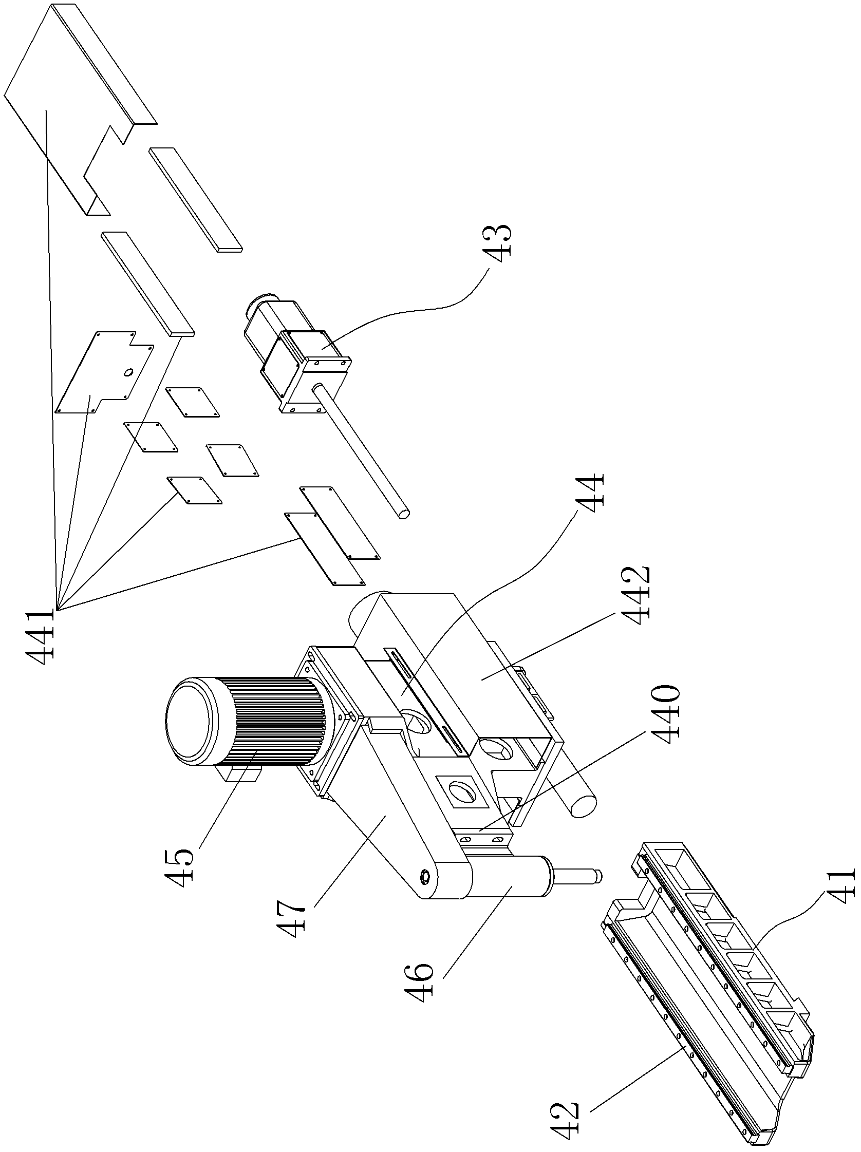
[0022] A sub-frame 3 is respectively provided on both sides of the main frame 1 , each of the sub-frames 3 is respectively provided with an arc-shaped slide rail 31 , and a tool holder assembly is respectively installed on the arc-shaped sl...


PUM


Abstract

The invention relates to a numerical control milling machine for curved surface machining of wood, comprising a main rack and an electric control console, wherein either of two sides of the main rack is provided with an auxiliary rack; an arc-shaped slide rail is respectively arranged on each auxiliary rack; tool apron assemblies are respectively arranged on the arc-shaped slide rails and comprise slide seats matched with the arc-shaped slide rails; second linear slide rails and second servo motor drive mechanisms are arranged on the slide seats; tool aprons driven by the second servo motor drive mechanisms are arranged on the second linear slide rails; tool bit driving motors and tool bit rotating shafts are arranged on the tool aprons; and the tool bit rotating shafts which are vertically arranged along longitudinal direction and used for arranging tool bits are driven by the tool bit driving motors through synchronous belt drive mechanisms. In the invention, two or more than two tool apron assemblies can be independently operated and can also be jointly operated, so that the flexibility is high and different forms of curved surface machining can be simultaneously carried out on the wood to ensure that the wood is more diversified in shapes and has wider application range.

Description

Technical field: [0001] The invention belongs to the technical field of mechanical equipment manufacturing, and relates to woodworking processing equipment, in particular to a numerical control milling machine for wood surface processing. Background technique: [0002] Surface processing of wood is a commonly used processing method in modern wood processing, and most efficient mechanical processing methods are currently used. In the existing woodworking equipment that can process curved surfaces, the cutter head seat for installing the cutter head is generally arranged on the upper part of the main frame, which can be moved up and down or can be translated in the horizontal plane. Do not move; in this type of surface processing equipment, multiple cutter heads are generally installed on the cutter head seat at the same time, each cutter head cannot be controlled independently, and the flexibility is poor. The workpiece is processed with different curved surfaces; and the to...

Claims


Application Information

Patent Timeline
Patent Type & Authority Applications(China)
IPC IPC(8): B27C5/10
Inventor 李一军
Owner 博罗县昶丰精密机械设备有限公司
Why Eureka
Try Eureka