Automatic hydraulic channeling machine

A grooving machine and hydraulic technology, which is applied in the field of automatic hydraulic grooving machines, can solve difficult problems such as groove technology, time-consuming and labor-intensive problems

Active Publication Date: 2012-07-04
浙江唯特利图伟管道设备有限公司
View PDF8 Cites 17 Cited by
  • Summary
  • Abstract
  • Description
  • Claims
  • Application Information

AI Technical Summary

Problems solved by technology

The entire work process is completely manual operation, which is time-consuming and labor-intensive

Method used


Image

  • Automatic hydraulic channeling machine
  • Automatic hydraulic channeling machine
  • Automatic hydraulic channeling machine

Examples


Embodiment Construction

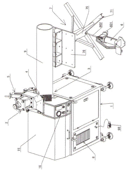
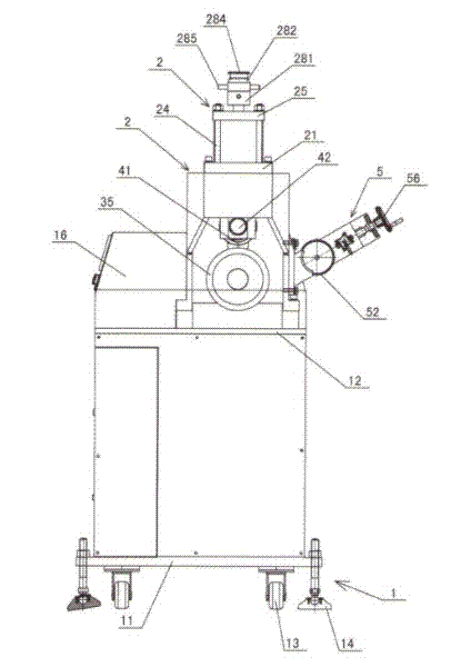
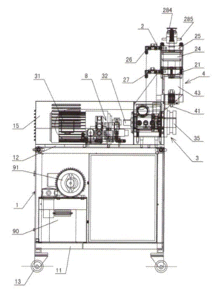
[0032] The invention relates to an automatic hydraulic grooving machine, such as Figure 1-Figure 18 As shown, it is characterized by including:

[0033] ① The frame part is equipped with 1, including the chassis 11, the table 12, the caster 13, the machine foot 14, the shield 15 and the panel 16;

[0034] ② Oil cylinder system 2, including oil cylinder base 21, piston rod 22, piston 23, cylinder body 24, oil cylinder upper end cover 25, upper and lower oil pipes 26, 27, adjustment nut 282, adjustment rod 285, lock nut 281, scale cover 284 ;

[0035] ③ Grooving mechanism 3, including main motor 31, power head 4, coupling 32, main shaft 33, bearing 34, knurling wheel 35, pressure roller guide shaft 43, pressure roller 41 and pressure roller shaft 42;

[0036] ④ guide wheel mechanism 4, including guide wheel shaft 51, guide wheel 52, sliding adjustment knob 53, adjustment bolt 54, guide block 55, hand wheel 56, screw mandrel 57, screw mandrel slider 58 and guide wheel frame 59...


PUM


Abstract

The invention relates to an automatic hydraulic channeling machine. A frame part comprises a chassis, a sole plate, a universal wheel, machine legs, a shield and a panel; a hydraulic system comprises a cylinder base, a piston rod, a piston, a cylinder body, an adjusting nut, an adjusting rod and a ruler sleeve; a channeling mechanism comprises a main motor, a power head, a coupler, a spindle, a bearing, a knurl wheel, a pressing wheel guide shaft, a pressing wheel and a pressing wheel shaft; a guide wheel mechanism comprises a guide wheel shaft, a guide wheel, a sliding adjusting knob, an adjusting bolt, a guiding block, a hand wheel, a screw rod, a screw rod slide block and a guide wheel frame; an electric system comprises a pedal switch, an alternated current contactor, an intermediate relay, a breaker, a rectifier, a transformer, a time relay, a buzzer and an indicator lamp; a hydraulic control system comprises an oil tank, an oil pump motor, a gear pump, an oil-way block, a solenoid directional valve, a pressure relay, a flow control valve and an overflow valve; and a working bracket comprises a bracket base, a bracket cylinder sleeve, a bracket cylinder base, a bracket cylinder, a bracket piston rod, a bracket plate, a bracket lifting device, a quick connector and a high-pressure oil pipe.

Description

technical field [0001] The invention relates to an automatic hydraulic grooving machine, which is mainly used for rolling annular grooves on the ends of various pipes such as seamless steel pipes, galvanized pipes, and plastic-lined pipes to install annular pipe clips, so as to achieve the purpose of quickly installing pipes. Machine tools for pipe installation in construction industry. Background technique [0002] In the water supply and drainage pipelines, the pipes need to be connected to each other. The traditional technology usually uses flange connection, but the flange connection needs to be welded first, and the second is to be fixed with fasteners. The installation is very troublesome and will cause problems. sparks, and fasteners such as screws are easy to loosen. Therefore, in recent years, rolling grooving machines have been used to roll the ends of pipes into annular grooves, and pipe clips are installed in the annular grooves. The hydraulic grooving process h...

Claims


Application Information

Patent Timeline
IPC IPC(8): B21D17/04
Inventor 杨岩顺
Owner 浙江唯特利图伟管道设备有限公司
Why Eureka
Try Eureka