

Method for lengthening wind power blade
A wind power blade and blade technology, which is applied in the field of lengthening wind power blades, can solve the problems of high cost and no economic benefits of technological upgrading.
- Summary
- Abstract
- Description
- Claims
- Application Information
AI Technical Summary
Problems solved by technology
Method used
Image

Examples
Embodiment 1
[0054] Step 1: Preliminary treatment of the existing blades.
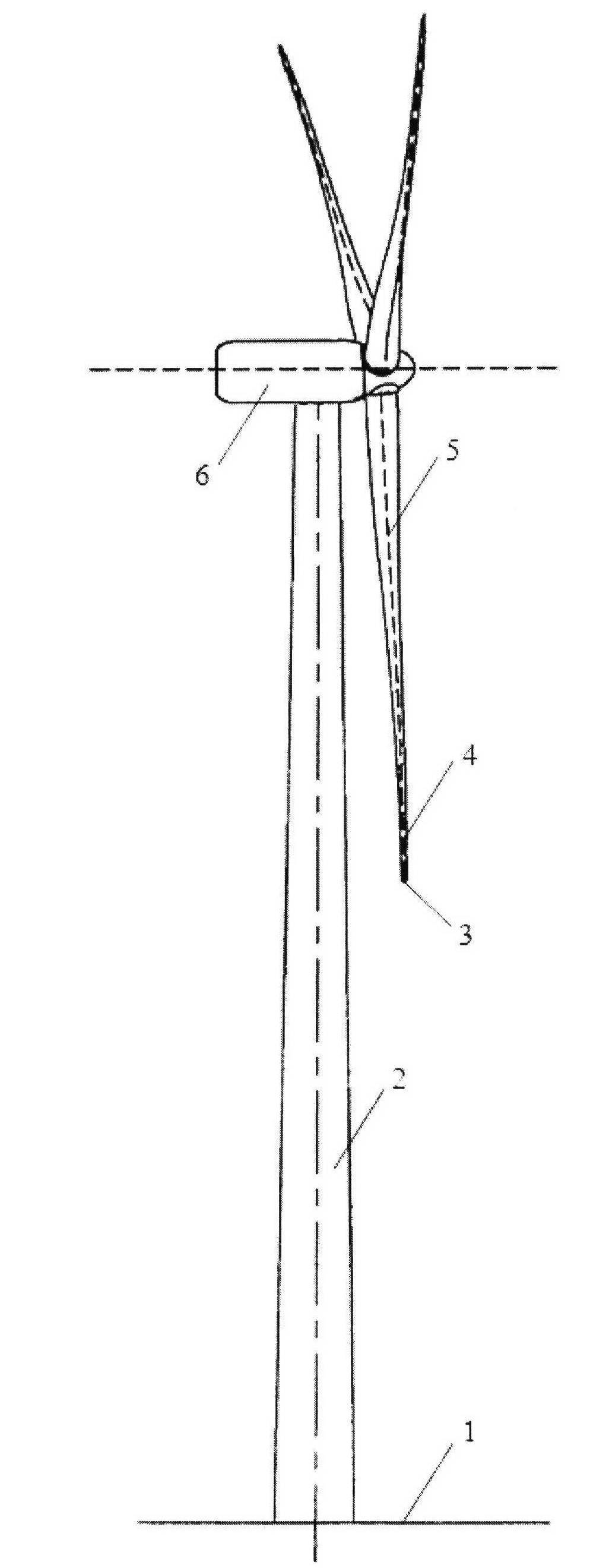
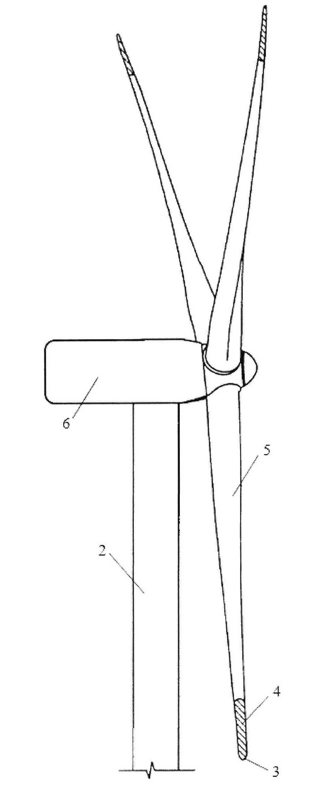
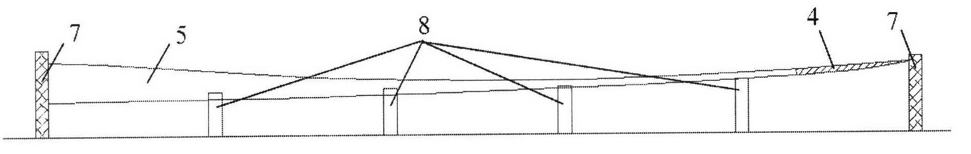
[0055] 1a. Place the existing blade 5 on the blade support frame 8;
[0056] 1b. Use a measuring tool such as a tape measure to measure the end position of the web 9 from the blade tip position;
[0057] 1c. Use a cutting tool such as an angle grinder to cut off the tip of the blade without the web at the end position of the web 9;
[0058] 1d. Measure a length of 0.01-2 meters from the above-mentioned truncation position, cut and / or polish off the shell (including the beam cap 10), and keep the web 9;
[0059] 1e. Clean up the dust at the tip of the blade 5 and store it for later use.
[0060] The second step: manufacturing accessories such as the blade tip shell and the web of the extension section.
[0061] 2a. Prepare two compatible blade tip shell female molds and a new set of blade tip web molds. After removing the debris on the mold surface, wipe the mold surface with mold cleaner and mold release agent; ...
Embodiment 2
[0077] Step 1: Preliminary treatment of the existing blades.
[0078] 1a. Place the existing blade 5 on the blade support frame 8;
[0079] 1b. Use a measuring tool such as a tape measure to measure the end position of the web 9 from the blade tip position;
[0080] 1c. Use a cutting tool such as an angle grinder to cut off the tip of the blade without the web at the end position of the web 9;
[0081] 1d. Cut and / or grind off a section of the shell (including the spar cap 10 ) from the above cut-off position, and keep the partially protruding web 12;
[0082] 1e. Clean up the dust at the tip of the blade 5 and store it for later use.
[0083] The second step: manufacturing accessories such as the blade tip shell and the web of the extension section.
[0084] 2a. Prepare two compatible blade tip shell female molds and a new set of blade tip web molds. After removing the debris on the mold surface, wipe the mold surface with mold cleaner and mold release agent;
[0085] 2b....
Embodiment 3
[0100] Step 1: Preliminary treatment of the existing blades.
[0101] 1a. Place the existing blade 5 on the blade support frame 8;
[0102] 1b. Using a tool such as a pneumatic grinder to roughen the surface of the tip of the existing blade that needs to be bonded;
[0103] 1c. Clean up the dust at the tip of the blade 5 and store it for later use.
[0104] The second step: manufacturing accessories such as the blade tip shell and the web of the extension section.
[0105] 2a. Prepare two compatible blade tip shell female molds and a new set of blade tip web molds. After removing the debris on the mold surface, wipe the mold surface with mold cleaner and mold release agent;
[0106] 2b. Paste the sealing tape on the edge of the mold flange;
[0107] 2c. Lay materials in the shell mold and web mold according to the layering sequence of each part;
[0108] 2d. Lay release cloth, diversion net and glue inlet pipeline on the surface of the laid product material at one time;
[...
PUM
 Abstract
Description
Claims
Application Information